16
most accurate measurement, the corresponding RC time constant must be stable to 1/50 of the input AC signal
level.
Signals greater than 300 V (RMS) or 1 A (RMS) can cause self-heating of the signal conditioning components.
These errors are included in the instrument's specifications. Internal temperature changes caused by self-heating
may cause additional errors in other functions or ranges. Additional errors typically disappear within a few
minutes. Take the 100 mVAC signal with a 10 VDC bias voltage as an example, the 10 VDC bias voltage should
be stable at 1/50 of 100mVAC or 1/50 of 2mVDC. The ACV function should be selected after the signal is
connected to the digital multimeter's ACV input or when the signal has been connected, enough extra delay should
be given to stabilize the signal. If the DC bias remains the same, a completely accurate subsequent measurement
can be made without additional stabilization delay.
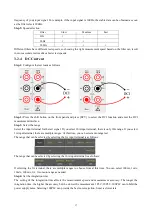
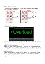
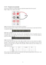
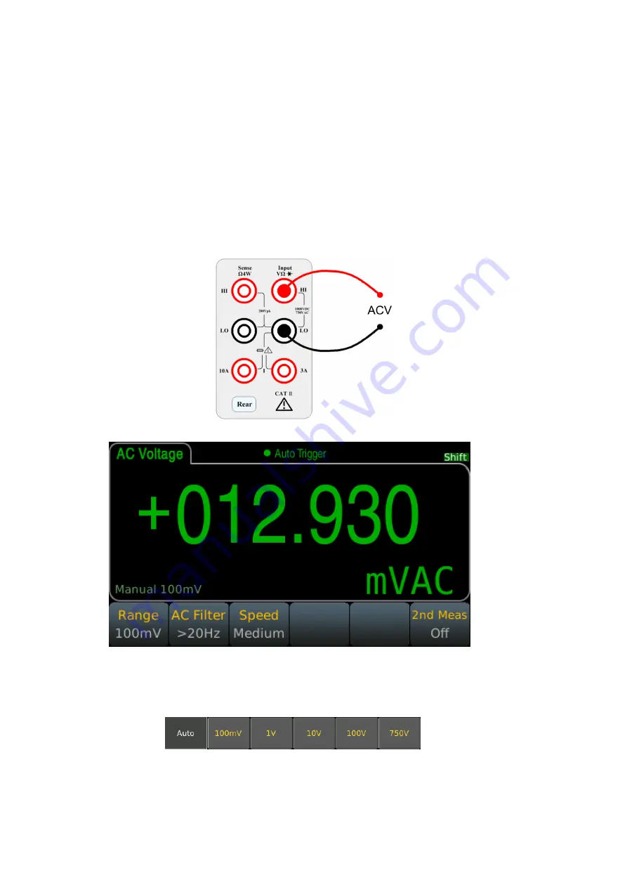
Step 1:
Configure the test leads as shown below.
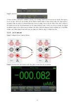
Step 2:
Press the [ACV] button on the front panel to enter the ACV test interface.
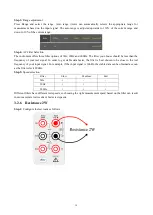
Step 3:
Range adjustment.
Press Range and select the range. Auto range (Auto) automatically selects the appropriate range for measurement
based on the input signal. The auto range is adjusted upwards to 110% of the current range and down to 10% of
the current range.
Step 4:
AC Filter Selection.
The instrument offers three filter options of 3Hz, 20Hz and 200Hz. The filter you choose should be less than the
frequency of your test signal. In order to get stable data faster, the filter is best chosen to be close to the test


