35
5.3 USB Interface
USB is short for universal serial bus. As one kind of the external bus standard, USB is used for the communication
between PC and external devices. In general, there are four wires:
Signal
Code
Color
Pin
Power
VCC
Red
1
Data
low-terminal
Data-
White
2
Data
high-terminal
Data+
Green
3
Grounding
GND
Black
4
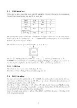
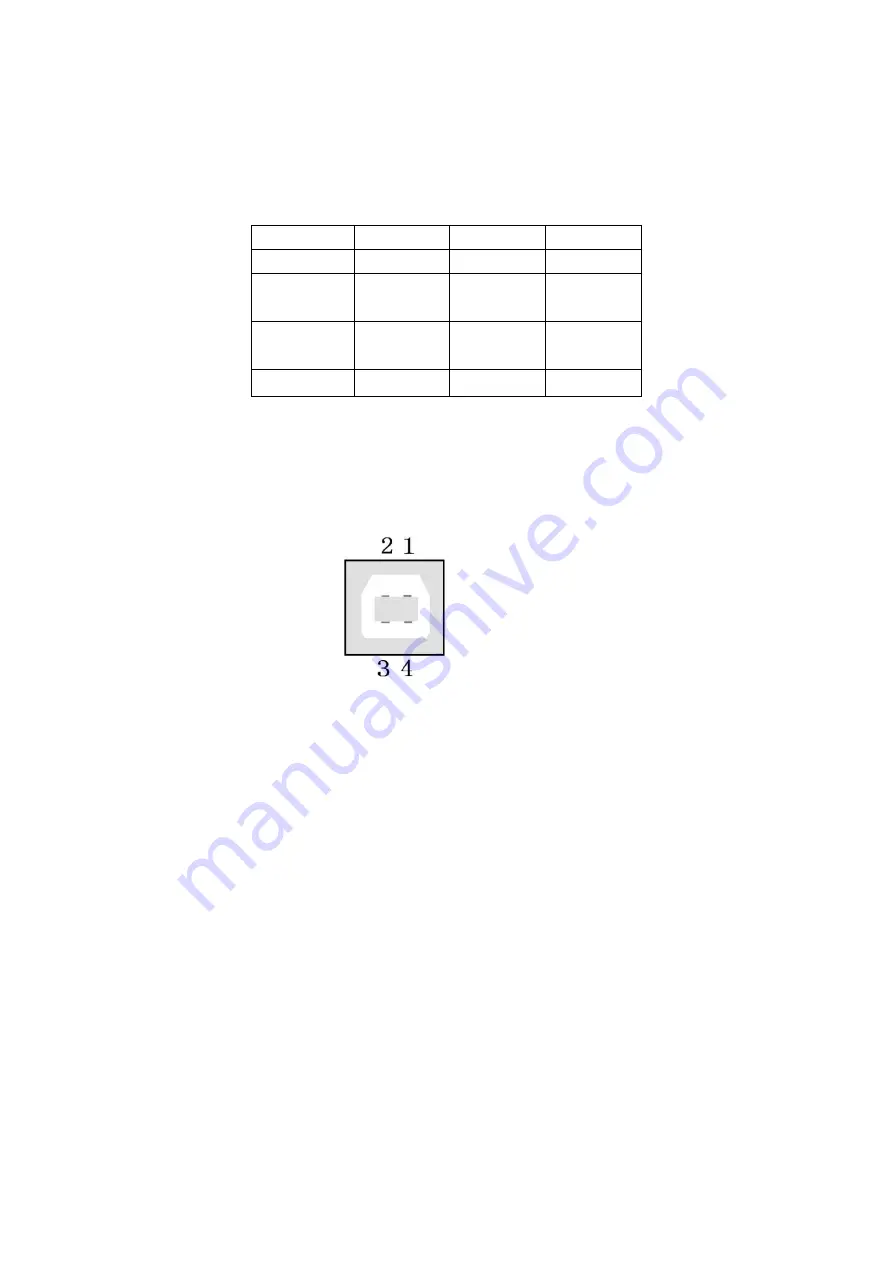
This instrument has total two USB interfaces on the front and rear panel. The latter serves as the communication
interface, that is, the instrument is used as a device. The USB interface on the front panel is used to read an USB
flash drive, the instrument is used as the host.
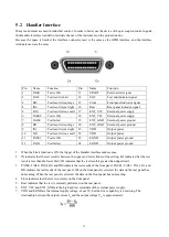
This instrument uses square type socket and the pin sequence is as follows:
This unit uses a USB-B type interface, which can communicate via a standard square USB interface cable.
CAUTION:
To avoid electrical shock, turn off the power supply when plugging or unplugging the connector; do
not short-circuit the output terminals or short-circuit with the chassis to avoid damage to the device.
5.3.1 USB Host
The instrument acts as a host to read and write data in the U disk.
Press Menu
→
Utility
→
Manage Files to see the file management unit.
5.4 LAN Interface
You may need to set a few parameters to use the LAN interface to establish network communication. First, you
need to create an IP address. You may need the help of your network administrator during the process of
establishing communication with the LAN interface.
Press Menu
→
Utility
→
I/O Config
→
LAN to Enter LAN Settings Screen. You can select
Modify
to change
the settings or restore LAN settings to its default values. You can also turn ON or OFF the WLAN service. If
turning on the WLAN, please insert the wireless network card first.
Some LAN setup functions can only be performed through SCPI. See SYSTem Subsystem - I/O Settings for all
LAN configuration commands.

