32
MSH/MPH series
Wiring instructions gage 12, 16
and 20 contact connectors
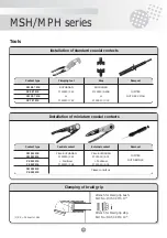
• Use the crimping tool and positioner specified.
Adjust the positioner to the wire gage.
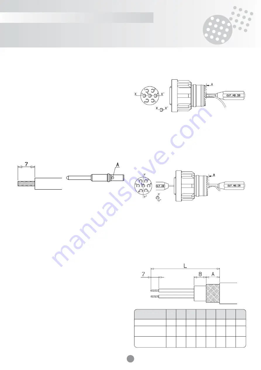
• Strip the wire to 7 mm.
• Insert the stripped end of the wire, placing the insulator against the rear
of the contact. Check that the conductor is visible through the contact
sight hole.
• Fully open the crimping tool.
• Insert the contact and the wire into the crimping tool.
• Fully close the crimping tool, and allow it to open.
• Check that the contact is correctly crimped. The wire must be visible
through the contact sight hole, and the wire insulator must be up
against the rear of the contact.
For crimping of coaxial contacts, depending on the cables used,
see the technical instructions supplied with each delivery of MS coaxial
connectors.
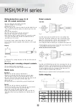
Stripping
A = “Sight hole” for checking the presence of the conductor before and
after crimping.
Installing and removing crimped contacts
• The use of plastic tools is recommended.
• The use of mechanical tools requires special care to avoid.
Plastic tools
Installation:
• Insert the wire into the channel on the plastic tool.
• Slide the tool along the wire to the stop on the contac shoulder.
Keep the wire taut so that the tool remains against the contact.
• Insert the contact into the housing from the rear of the connector, and
push the tool in as far as it will go, until the contact locks.
• Remove the tool.
• Pull gently on the wire to check that the contact is firmly attached.
Removal:
• Insert the wire into the channel on the plastic tool.
• Slide the tool along the wire so that it enters the connector insulator
and comes to a stop against the rear contact shoulder.
• Remove the tool and the contact at the same time.
• If there is any resistance before freeing the contact, move the tool
backwards, without removing it altogether, turn it slightly, and put it
back in.
Metal contacts
Installation
Insert the contacts into the insulator from the rear by pushing them
in using tool OUT-MB-DB, with the part number corresponding to the
gage of the contact used (fig. 5). This tool must be aligned such that
its XX axis is parallel with the marking on the insulator (fig. 2).
It is recommended that the assembly tool be lubricated before each use.
• If slight resistance encountered, do not force the tool, but check that it
is perpendicular to the plane of the insulator.
• Never turn the tool in the insulator.
Insert the tool OUT.MB.DB appropriate to the contact gage from the rear,
aligned such that its YY axis is perpendicular to the marking on the insu-
lator (fig. 5), in order to free the contact. Once this tool is in place, with
its opening always pointing down in relation to the number, push the
contact out using the corresponding OUT.DB tool.
Note :
the same care should be taken as with installation of contacts.
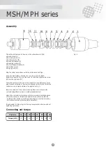
Cable stripping
Fig. 1
Fig. 2
Fig. 3
Fig. 4
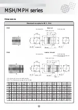
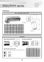
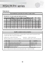
Shell size
16
17
18
20
22
24
26
28
a
10
10
10
10
10
10
13
15
Straight
backshell L
56
61
71
76
84
89
96
96
Elbow
backshell L
79
94
109
119
134
144
154 169

