-44-
For Machines Mfd. Since 12/21
South Bend Tools
Model SB1007
O P E R A T I O N
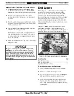
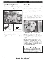
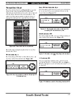
Figure
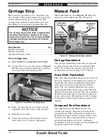
Figure 59. Feed selection lever positions.
. Feed selection lever positions.
Cross Slide
Disengaged
Feed Control
Lever
Carriage
In the middle position, the apron gears are
disengaged from the feed rod and neither
component will move.
D. Feed Selection Lever Indicator:
Arrow
symbols that visibly indicate carriage or
cross feed selection.
Setting Power Feed Rate
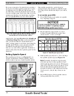
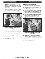
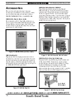
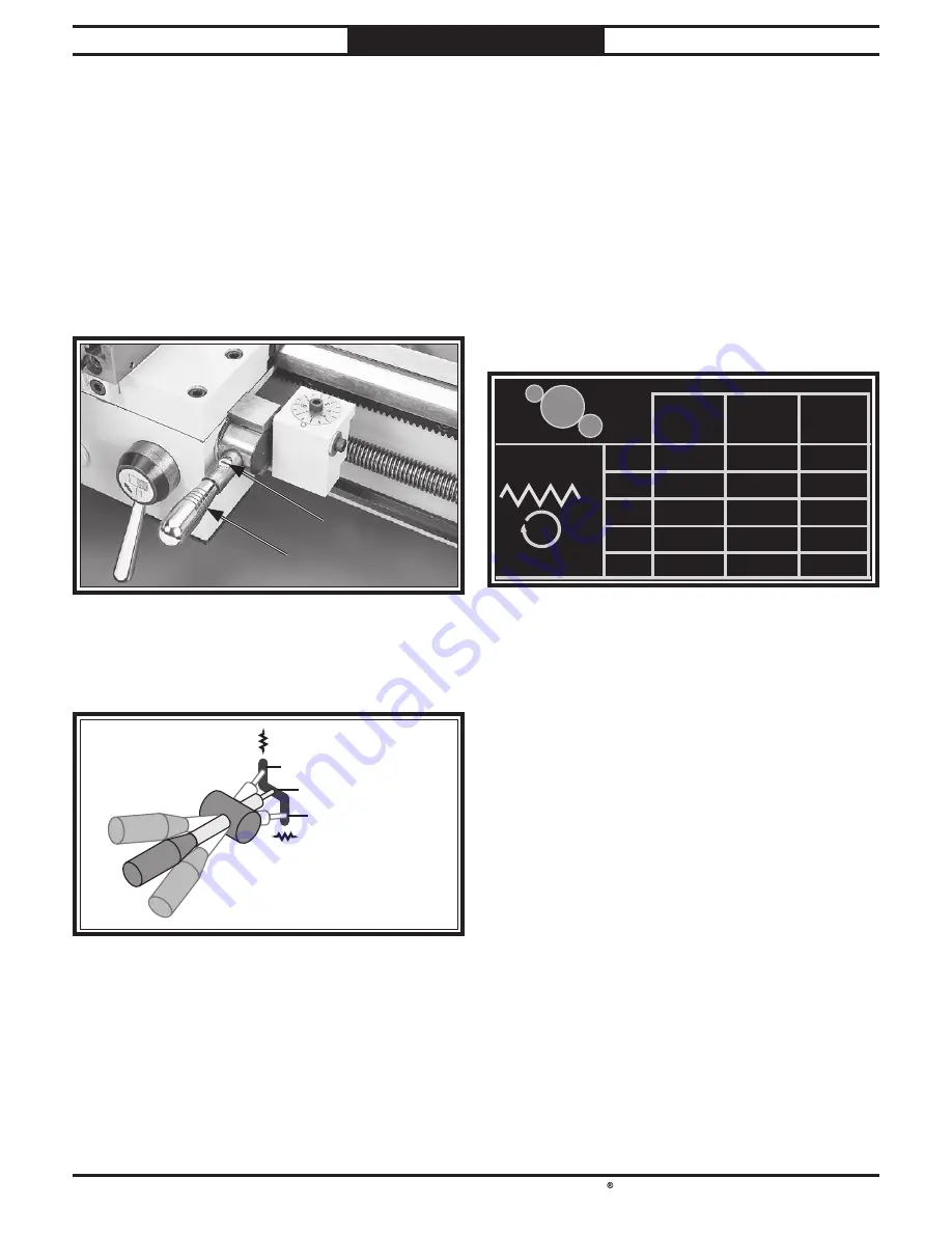
The feed rate chart in Figure 60 is also
displayed on the quick change gearbox cover. It
displays the end gear and quick-change gearbox
knob settings for inch feed rates.
A
B C
A
A
B C
1
2
3
4
5
1
2
3
4
5
1
2
3
4
5
.0018
.0020
.0024
.0029
.0032
.0040
.0048
.0058
.0064
64
56
48
40
36
32
28
24
20
18
.0036 .0072
.0080
.0096
.0116
.0128
0.5
0.6
0.75
1.0
1.5
2.0
16
14
12
10
9
3
5 1 4
2
A C B
C
B
127
90
90
120
30
127
30
90
127
30
INCHES
INCHES
MM
Figure
Figure 60. Feed rate chart.
. Feed rate chart.
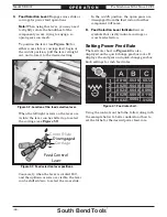
Using the controls on the lathe, follow along with
the example below to better understand how to
set the lathe for the desired power feed rate.
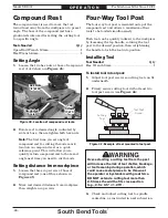
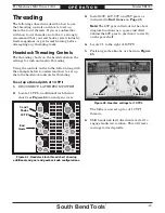
C. Feed Selection Lever:
Engages cross slide or
carriage for power feed operations.
Note:
When using this lever, you may need
to slightly rotate the handwheel of the
component you are trying to engage, so
apron gears can mesh.
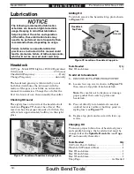
To position the lever (see Figure 58) for
either cross slide or carriage feed, begin at
the middle position, pull the lever straight
out, and rotate it to the desired setting.
Figure
Figure 58. Location of the feed selection lever.
. Location of the feed selection lever.
D
D
C
C
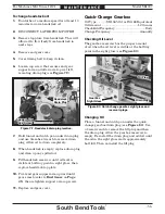
When the left/right arrows on the lever are
visible, the lever can be shifted up to select
the carriage (see Figure 59).
Conversely, when the lever is rotated 180˚,
and the up/down arrows are visible, the lever
can be shifted down to select the cross slide.

