South Bend Tools
For Machines Mfd. Since 12/21
Model SB1007
-45-
O P E R A T I O N
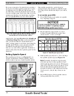
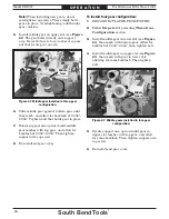
Setting Power Feed Rate of 0.0018 in./rev.:
1.
Make sure end gears are in configuration
indicated on feed rate chart (refer to End
Gears on this page for detailed instructions).
2.
Locate box on feed rate chart that lists
setting for 0.0018" of feed per revolution of
spindle.
3.
Rotate quick-change gearbox knobs to alpha-
numeric settings indicated on feed rate chart
(in this instance, 1A).
4.
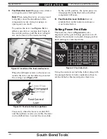
Use headstock feed direction lever to select
direction of carriage travel.
When lever is to the left, carriage will move
toward the spindle. Conversely, when lever
is to the right, the carriage will move away
from the spindle.
5
. Shift feed selection lever up to select carriage
for power feed.
To prevent damage to gearbox components,
NEVER move levers while lathe is running,
and NEVER force any lever when shifting. If
lever will not engage, rotate chuck by hand
while keeping light pressure on the lever. As
chuck rotates, it aligns the gears and the lever
will engage.
End Gears
The end gears on this lathe can be configured
according to the operation to be performed:
power feed and inch or metric threading. The
operation you choose will determine which
gear configuration you must use. This includes
the number of gears—either three or four—
and the tooth count of each gear. The SB1007
lathe arrives from the factory in the three-gear
configuration.
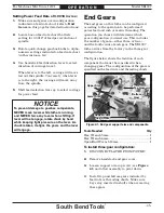
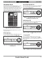
The figure below shows the location of each
component that must be considered when
changing gears. The configuration of the gears is
specified on the feed rate and threading charts.
Tools Needed
Qty
Hex Wrench 5mm .................................................1
Hex Wrench 6mm .................................................1
Open-End Wrench 13mm .....................................1
To install three-gear configuration:
1.
DISCONNECT LATHE FROM POWER!
2.
Remove headstock end gear cover.
3.
Loosen support arm cap screw (see Figure
61) and allow assembly to pivot down.
4
. Install top and bottom gears indicated by
feed rate or threading charts. Make sure
keys stay inserted in shafts when removing
these gears.
Figure
Figure 61. End gear support arm and components.
. End gear support arm and components.
Bottom
Bottom
Gear
Gear
Top Gear
Top Gear
Support Arm
Support Arm
Cap Screw
Cap Screw
Lower Slot
Lower Slot
Upper Slot
Upper Slot

