-20-
For Machines Mfd. Since 11/20
South Bend Tools
Model SB1099
P R E P A R A T I O N
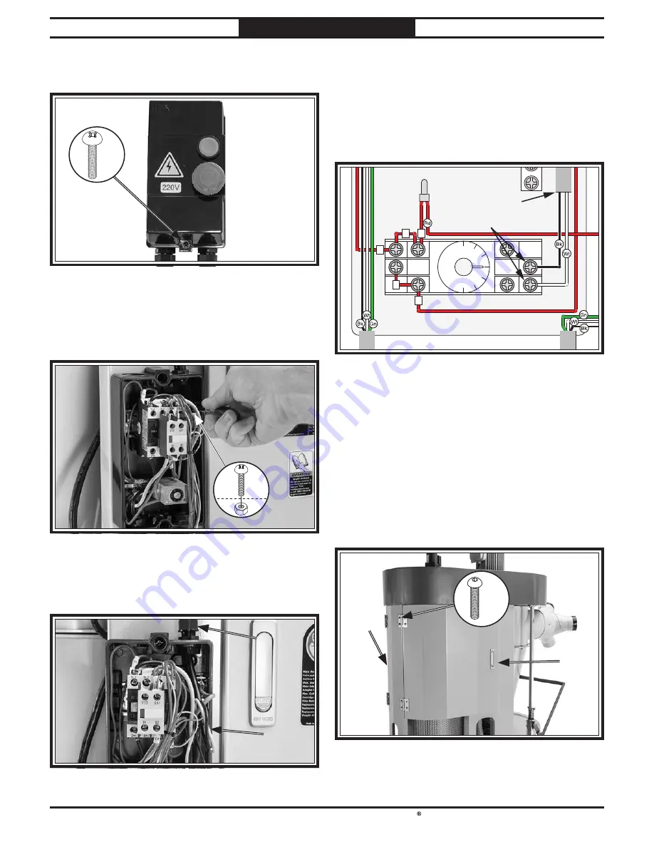
33.
Loosen (2) Phillips head screws and remove
switch box cover (see Figure 28).
Figure
Figure 28. Switch box.
. Switch box.
x2
x2
34.
Attach switch box to side panel underneath
pressure gauge with
(2) 10-24 x
3
⁄
4
" Phillips
head screws and (2) 10-24 hex nuts
(see
Figure 29).
Figure
Figure 29. Attaching switch box to side panel.
. Attaching switch box to side panel.
x2
x2
Figure
Figure 30. Filter brush motor cord routed into switch
. Filter brush motor cord routed into switch
box.
box.
35.
Pull motor cord from filter brush motor
through strain relief at top of switch box (see
Figure 30).
Motor
Motor
Cord
Cord
Strain
Strain
Relief
Relief
36.
Connect terminal ends of motor cord to right
terminals of timer inside switch box (see
Figure 31).
Note: Timer module may be pulled off
terminal block if it is in the way during
connection of motor cords.
Figure
Figure 31. Filter brush motor connection.
. Filter brush motor connection.
AMY-2 5A 250VAC
0
1
2
3
AMY
24
0
VA
C
A
N
LY
Ground
2
2
1
1
1
Timer
Motor Cord
Connect
Note: For full wiring diagram refer to Wiring
Diagram on Page 43.
37.
Tighten strain relief (see Figure 30) to
secure motor cord in position.
38.
Attach cover of switch box.
40.
Repeat Step 39 with right filter door.
Figure
Figure 32. Filter door installed to rear panel.
. Filter door installed to rear panel.
39.
Attach left filter door to rear panel with (4)
5
⁄
16
"-18 x
1
⁄
2
" button head cap screws (see
Figure 32).
x4
x4
Filter
Filter
Door
Door
Rear
Rear
Panel
Panel


