background image

-60-

For Machines Mfg. Since 8/09

SB1024/SB1025/SB1026

S E R V I C E

Figure 65. Ball handle, rings, and key removed from 

the cross leadscrew.

Cross Leadscrew

4.

  Remove the four cap screws from the bearing 

housing, then slide it off the leadscrew (see 

Figure 66).

Note:

 It may be necessary to use a dead blow 

hammer or rubber mallet on the housing to 

knock it loose.

Figure 66. Removing the bearing housing from the 

cross leadscrew.

Bearing

Housing

5.

  Loosen the two cap screws on the face of the 

leadscrew nut shown in Figure 67.

Figure 67. Cross leadscrew nut and cap screws.

Cross Leadscrew

Nut & Cap Screws

6.

  Re-install the key back onto the leadscrew so 

that you can use the ball handle in the next 

step.

7.

  Rotate the adjustment plate on the 

leadscrew nut in small increments, then 

check the amount of backlash.

8.

  When you are satisfied with the adjustment, 

re-tighten the two cap screws.

9.

  Re-install the parts previously removed in 

the reverse order.

Cross Leadscrew Backlash

1.

  DISCONNECT MILL FROM POWER!

2.

  Remove the hex nut and ball handle from the 

cross leadscrew.

Note:

 In the next step, take care not to misplace 

the leadscrew key as you remove the parts.

3.

  Unthread and remove the knurled retaining 

ring, graduated dial ring, and the leadscrew 

key, as shown in Figure 65.

Summary of Contents for SB1025F

Page 1: ...ling machine you MUST read and understand this insert the entire Model SB1025 Owner s Manual and the Fagor DRO Owner s Manual to reduce the risk of injury when using this machine If you have any furth...

Page 2: ...r Requirement 220V 3 Phase 60 Hz Prewired Voltage 220V Full Load Current Rating 6A Minimum Circuit Size 15A Connection Type Cord Plug Power Cord Included No Recommended Power Cord S Type 4 Wire 14 AWG...

Page 3: ...te 0 3 34 FPM X Y Axis Travel per Handwheel Revolution 0 200 in Z Axis Travel per Handwheel Revolution 0 100 in Spindle Info Spindle Taper R 8 Number of Vertical Spindle Speeds 16 Range of Vertical Sp...

Page 4: ...to Downfeed Stop with Micro Adjustable Stop Variable Speed Longitudinal Power Feed Hardened and Precision Ground Table Surface Chromed Steel Quill Heavy Duty Spindle Brake Halogen Work Light Allen Bra...

Page 5: ...sed March 2015 ST For Machines Mfg Since 8 09 MODEL SB1024 VARIABLE SPEED 220V SINGLE PHASE MODEL SB1025 220V 3 PHASE MODEL SB1026 220V SINGLE PHASE 9 X 42 MILLING MACHINE w POWER FEED MODEL SB1024 MO...

Page 6: ...s of operation is a process that happens through training and experience If you are not an experienced operator of this type of machinery read through this entire manual then learn more from an experi...

Page 7: ...ction 24 SB1024 220V 24 SB1025 220V 3 Phase 24 SB1026 220V 24 Initial Lubrication 25 Test Run 25 Spindle Break In 27 Inspections Adjustments 27 OPERATION Operation Overview 28 Control Panel 29 Table M...

Page 8: ...Panel 91 Accessories 92 SB1024 Head Machine Labels 93 SB1024 Main Machine Labels 94 SB1025 SB1026 Machine Labels 95 WARRANTY RETURNS 97 Ram Ways 54 Head Ram Rack Pinion Gear 54 Table Elevation Leadsc...

Page 9: ...tary dial phone television set mechanical calculator computer and camera of that decade could barely fit into one large room together now they fit into a tiny box that is no bigger than a box of breat...

Page 10: ...Model SB1024 shown Halogen Work Light Left X Axis Ball Handle One Shot Oiler Mounting Points 1 of 4 Y Axis Ball Handle Knee Electrical Cabinet Right X Axis Ball Handle Slotted Work Table Power Feed Li...

Page 11: ...Lever Dial Indicator Rod Quill Adjustable Downfeed Stop Downfeed Clutch Lever Fine Downfeed Handwheel Auto Downfeed Direction Pin Auto Downfeed Rate Selector Spindle Brake SB1024 belt housing headsto...

Page 12: ...ever Dial Indicator Rod Quill Adjustable Downfeed Stop Downfeed Clutch Lever Fine Downfeed Handwheel Auto Downfeed Rate Selector Auto Downfeed Direction Pin Figure 3 Model SB1025 SB1026 belt housing a...

Page 13: ...ght 1984 lbs Length x Width x Height 54 x 54 x 73 in Electrical Power Requirement 220V Single Phase 60 Hz Prewired Voltage 220V Full Load Current Rating 14A Minimum Circuit Size 20A Connection Type Co...

Page 14: ...rs 2 1 2 in Number of Longitudinal Feeds Variable X Axis Table Power Feed Rate 0 3 34 FPM X Y Axis Travel per Handwheel Revolution 0 200 in Z Axis Travel per Handwheel Revolution 0 100 in Spindle Info...

Page 15: ...s Length x Width x Height 54 x 54 x 74 in Electrical Power Requirement 220V 3 Phase 60 Hz Prewired Voltage 220V Full Load Current Rating 6A Minimum Circuit Size 15A Connection Type Cord Plug Power Cor...

Page 16: ...nters 2 1 2 in Number of Longitudinal Feeds Variable X Axis Table Power Feed Rate 0 3 34 FPM X Y Axis Travel per Handwheel Revolution 0 200 in Z Axis Travel per Handwheel Revolution 0 100 in Spindle I...

Page 17: ...ht 2140 lbs Length x Width x Height 54 x 54 x 73 in Electrical Power Requirement 220V Single Phase 60 Hz Prewired Voltage 220V Full Load Current Rating 14A Minimum Circuit Size 20A Connection Type Cor...

Page 18: ...enters 2 1 2 in Number of Longitudinal Feeds Variable X Axis Table Power Feed Rate 0 3 34 FPM X Y Axis Travel per Handwheel Revolution 0 200 in Z Axis Travel per Handwheel Revolution 0 100 in Spindle...

Page 19: ...lows Death or catastrophic harm WILL occur Moderate injury or fire MAY occur Death or catastrophic harm COULD occur Machine or property damage may occur Basic Machine Safety Owner s Manual All machine...

Page 20: ...verifying that all fastening devices are properly secured and items attached to spindles have enough clearance to safely rotate Chuck Keys or Adjusting Tools Tools used to adjust spindles chucks or an...

Page 21: ...illing results and reduces the risk of personal injury from broken tool debris Inspect cutting tools for sharpness chips or cracks before each use and ALWAYS make sure the cutting tools are firmly hel...

Page 22: ...o Page 24 for details For Assembly Cotton disposable rags Cleaner degreaser see Page 18 Safety glasses for each person The purpose of the preparation section is to help you prepare your machine for op...

Page 23: ...r than the mill have been removed from the shipping crate you should have the following inventory Description Figure 4 Qty A Front Way Cover 1 B Rear Way Cover 1 C Fine Downfeed Handwheel 1 D Drawbar...

Page 24: ...e to make sure they will not damage it Basic steps for removing rust preventative 1 Put on safety glasses and disposable gloves 2 Coat all surfaces that have rust preventative with a liberal amount of...

Page 25: ...manual Physical Environment The physical environment where your machine is operated is important for safe operation and longevity of parts For best results operate this machine in a dry environment th...

Page 26: ...strated in Figure 6 refer to Ram Movement on Page 36 and Headstock Movement on Page 32 for detailed instructions Note After re positioning the ram and headstock make sure they are locked in place to p...

Page 27: ...g and sensitive enough to show a distinct movement when a 0 003 shim approximately the thickness of one sheet of standard newspaper is placed under one end of the level See the figure below for an exa...

Page 28: ...leadscrew key then slide it onto the leadscrew 4 Secure the ball handles with the hex nuts removed in Step 1 Note Tighten the hex nuts just until they are snug Overtightening could increase the wear o...

Page 29: ...le and knee position the pleated way cover in place then secure it with the removed cap screws 2 Remove the four button head cap screws shown in Figure 12 from the column and the rear of the table pos...

Page 30: ...ages 65 68 4 We recommend that you connect the other end to a NEMA 6 20 plug SB 1024 26 or NEMA L15 20 plug SB1025 Electrocution or fire may occur if machine is ungrounded incorrectly connected to pow...

Page 31: ...ecific details 4 Set the spindle speed to the low range refer to the Setting Spindle Speed Range section beginning on Page 37 for detailed instructions The machine was fully lubricated at the factory...

Page 32: ...ate as expected during the following steps disconnect it from power and contact our Tech Support at 360 734 1540 for assistance To test the X axis power feed unit and table limit switch 1 Make sure al...

Page 33: ...ure trouble free performance from the mill To perform the spindle break in procedure 1 Successfully perform all the steps in the Test Run section beginning on Page 25 2 Make sure the spindle is at a c...

Page 34: ...irm the correct positioning of the cutting tool and workpiece for the operation If the X axis power feed will be used during the operation the operator confirms the speed and length of table movement...

Page 35: ...or each direction that electronically change the speed of the motor and work in conjunction with the belt housing controls to set the spindle speed range refer to To set the spindle speed range for th...

Page 36: ...tion X 0 001 0 200 Y 0 001 0 200 Z 0 001 0 100 Table Locks Refer to Figure 19 for the locations of the locks used to secure the table in place Figure 18 Graduated table index rings Index Rings Always...

Page 37: ...when positioned 3 Turn the speed dial all the way counterclockwise to slowest setting move the directional lever to neutral middle position then flip the power switch up to turn the unit ON 4 With yo...

Page 38: ...ree tilt lock bolts on the right side of the ram adapter shown in Figure 23 Figure 23 Head tilting controls Lock Bolts Tilt Bolt 3 Use one hand to apply pressure to the head in the direction of rotati...

Page 39: ...to ensure the spindle is exactly 90 to the table This procedure involves mounting a dial test indicator to the quill or spindle rotating it around the table and adjusting the spindle axis Z axis 90 to...

Page 40: ...tramming preferably centered to the saddle Tighten any table knee quill or ram locks that should be tight during the intended milling operation 3 Place the parallel block underneath the spindle Figure...

Page 41: ...ou adjust it small amounts Remember to tighten the rotation lock bolts after adjusting the head Figure 28 Parallel block positioned for the Y axis measurement top view Parallel Block Indicator Spindle...

Page 42: ...in place Always lock the head firmly in place after tilting or rotating it Unexpected movement of the head during operations could cause damage to the cutter or workpiece Ram Movement The ram travels...

Page 43: ...Using the correct spindle speed is important for safe and satisfactory results as well as maximizing tool life To set the spindle speed for your operation you will need to 1 Determine the best spindl...

Page 44: ...e speed range that includes the required spindle speed for your operation Model SB1024 Spindle Speed Ranges Low Range 60 500 RPM High Range 500 4200 RPM When the spindle speed range is changed the dir...

Page 45: ...to avoid damaging the machine and voiding the warranty Model SB1025 Spindle Speed Ranges Low Range w Switch F1 R1 80 325 RPM Low Range w Switch F2 R2 160 650 RPM High Range w Switch F1 R1 710 2800 RPM...

Page 46: ...spindle pulley and pinion are properly seated into the bull gear When setting the mill to use the high spindle speed range the front spindle pulley must mesh with the spindle clutch Otherwise you will...

Page 47: ...tart the spindle rotation 2 Slowly rotate the speed handwheel shown in Figure 34 until the desired speed is displayed in the speed indicator window for the speed range selected For the Model SB1024 ON...

Page 48: ...ightly different spindle speeds for each V belt position Make sure you refer to the correct illustration for the mill Also Model SB1025 has two spindle speeds for each V belt position that are selecte...

Page 49: ...wnfeed movement on the mill is controlled by three mechanisms 1 The coarse downfeed handle 2 the fine downfeed handwheel and 3 the auto downfeed system Using the Coarse Downfeed Handle 1 Make sure tha...

Page 50: ...tion 4 Make sure the pin of the coarse downfeed handle hub is engaged with one of the detents on the downfeed sleeve see Figure 40 5 Make sure the quill lock lever is loose so that the quill can easil...

Page 51: ...The stop is threaded into position then the locking wheel is use to secure it in place H Quill Dog Moves with the quill and spindle and disengages the downfeed clutch lever when it engages either the...

Page 52: ...el that is correct for your operation It may be necessary to rock the fine downfeed handwheel back and forth to move the pin all the way in or out Note The direction pin has three positions 1 In for o...

Page 53: ...ndle travel To avoid the risk of gear damage always start spindle rotation before using the auto downfeed rate selector Figure 43 Positions of the auto downfeed rate selector M L H H 0 006 in rev L 0...

Page 54: ...pindle taper then firmly push the tool into the spindle to seat it Figure 46 Spindle drawbar and spacer Spacer 5 With one hand holding the tool in place insert the drawbar into the spindle from the to...

Page 55: ...ect machine from power before performing maintenance or serious personal injury may result Before Beginning Operations Make sure the electric box door is closed and properly latched Turn the spindle d...

Page 56: ...Keep each charts as a maintenance record for the mill 360 734 1540 FAX 360 676 1075 www southbendlathe com South Bend Lathe Co Monthly Maintenance Chart for Model SB1024 SB1025 SB1026 Mills 1 2 3 4 5...

Page 57: ...y 40 hrs 53 Headstock Gearing 40 hrs 53 Ram Ways 40 hrs 54 Table Elevation Leadscrew Z Axis 40 hrs 54 Power Feed Gears 160 hrs 54 Figure 48 Recommended lubrication tasks schedules and instruction page...

Page 58: ...lure of the mill and will void the warranty Table Ways One Shot Oiler Oil Type Mobil Vactra 2 or ISO 68 Equivalent Oil Amount One Pull of Pump Handle Check Add Frequency 4 8 hrs of Operation The one s...

Page 59: ...dd 5 drops of lubricant Figure 51 Speed range bearing sleeve SB1024 only Oil Cup Headstock Gearing Grease Type NLGI 2 or Equivalent Grease Amount Two Pumps of Grease Gun Check Add Frequency 40 hrs of...

Page 60: ...ump from a grease gun to the leadscrew grease fitting shown in Figure 56 then run the knee up and down to distribute the grease Repeat this process until the entire leadscrew Power Feed Gears Grease T...

Page 61: ...ght coat of lubricant on the teeth of the bevel gear and the smaller drive gear see Figure 59 6 Replace the leadscrew alignment key then align the bevel gear keyway and the key as you slide the gear o...

Page 62: ...or 4 Place the catch pan under the drain plug then remove the plug and allow the fluid to drain into the pan 5 Clean away debris and grime from the coolant drain screens on the base of the mill 6 Use...

Page 63: ...nted surfaces Note If the machine will be out of service for only a short period of time use way oil or a good grade of medium weight machine oil not auto engine oil in place of the grease or rust pre...

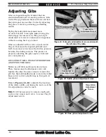
Page 64: ...e sliding surfaces The process of properly adjusting the gibs requires trial and error and patience DISCONNECT MILL FROM POWER BEFORE ADJUSTING THE GIBS Make sure all table and knee locks are loose Th...

Page 65: ...remature thread wear However if you find it necessary to adjust leadscrew backlash perform the procedures listed below Tools Needed Qty T Handle Hex Wrench 5mm 1 Hex Wrench 3mm 2 Hex Wrench 8mm 1 Wren...

Page 66: ...ross leadscrew nut and cap screws Cross Leadscrew Nut Cap Screws 6 Re install the key back onto the leadscrew so that you can use the ball handle in the next step 7 Rotate the adjustment plate on the...

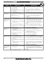
Page 67: ...e spindle speed Page 37 5 Motor connection wired incorrectly 5 Correct motor wiring connections Pages 66 69 6 Plug receptacle is at fault or wired incorrectly incorrect voltage coming from power sourc...

Page 68: ...cure the tool replace if damaged 4 Spindle speed too fast feed rate too slow 4 Use correct spindle speed and feed rate Page 37 5 Gibs are too loose 5 Properly adjust gibs Page 58 Table hard to move 1...

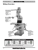
Page 69: ...ions 3 Modifications Using aftermarket parts or modifying the wiring beyond what is shown in the diagram may lead to unpredictable results including serious injury or fire 4 Motor Wiring The motor wir...

Page 70: ...GE YELLOW YELLOW GREEN PURPLE PINK LIGHT BLUE BLUE WHITE TUR QUIOSE NOTICE WIRING DIAGRAM COLOR KEY Motor Junction Box SB1024 SB1026 See Page 66 and Figure 70 SB1025 See Page 69 and Figure 74 Work Lam...

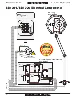
Page 71: ...T3 NC 21 NC 22 NC 2 4 6 T1 T2 T3 2 4 6 8 T1 T2 T3 T4 L3 T1 35 22 21 10 8 4 3 2 1 U V W L1 L1 L1 W W W V V V U U R R R R T T T T T 9 2 R U T1 T1 T1 T1 T1 T1 1R 1R 3R 3R 3R 3R T1 T1 35 35 20 20 22 22 2...

Page 72: ...ended 220 VAC G X1 X2 1 2 1 2 X1 X2 3 4 3 4 3 4 T1 T1 T1 T1 10 10 8 8 4 4 4 4 4 4 3 3 3 3 2 2 2 2 1 1 1 1 Power Indicator Emergency Stop Spindle Start Spindle Stop Spindle Direction SB1024 SB1026 Elec...

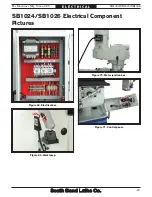
Page 73: ...hines Mfg Since 8 09 SB1024 SB1025 SB1026 67 E L E C T R I C A L Figure 68 Electrical box Figure 69 Work lamp Figure 70 Motor junction box Figure 71 Control panel SB1024 SB1026 Electrical Component Pi...

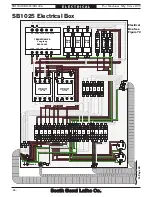
Page 74: ...Fuse 5A CONTACTOR Allen Bradley C09 400 A1 A2 1 3 5 7 L1 L2 L3 L4 2 4 6 8 T1 T2 T3 T4 2 4 6 8 T1 T2 T3 T4 Ground Fuse 20A W L1 L2 L3 L1 W V U R R R R S S T R T T T T1 T1 T1 T1 T1 W V U T1 1R 3R 3R 3R...

Page 75: ...X1 X2 3 9 13 1 5 17 21 12 16 4 8 20 24 4 1 2 2 1 11 15 3 7 19 23 10 14 2 6 18 22 W1 W2 U2 U2 U1 U1 V2 V2 V1 V1 W W V V U U 4 4 4 1 1 1 1 3 3 3 3 2 2 2 2 T1 T1 T1 T1 GND W1 W1 V1 V1 U1 U1 U2 U2 V2 V2 W...

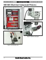
Page 76: ...fg Since 8 09 SB1024 SB1025 SB1026 E L E C T R I C A L Figure 72 SB1025 Electrical box Figure 73 SB1025 Work lamp Figure 74 SB1025 Motor junction box SB1025 Electrical Component Pictures Figure 75 SB1...

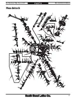
Page 77: ...45 46 47 48 49 50 51 52 53 54 55 56 57 58 59 60 61 62 63 64 65 66 67 68 69 70 71 72 73A 74 75 76 78 79 80 81 82 83 84 85 86 87 88 89 90 91 92 93 94 95 96 97 98 99 100 101 102 103 104 105 106 107 108 1...

Page 78: ...UT 71 PSB10240071 OVERLOAD CLUTCH WORM GEAR 30T 25 PSB10240025 WORM SHAFT 72 PR05M EXT RETAINING RING 15MM 26 PSS01M SET SCREW M6 1 X 10 73 PSB10240073A PINION OVERLOAD CLUTCH SHAFT 27 PK102M KEY 4 X...

Page 79: ...40105A QUILL MICRO STOP ASSEMBLY 124 PSB10240124 FINE DOWNFEED HANDWHEEL 105 PSB10240105A QUILL MICRO STOP SHAFT 125 PSB10240125 HANDWHEEL HANDLE 106 PCAP105 CAP SCREW 3 8 16 X 5 8 126 PEC13M E CLIP 5...

Page 80: ...1 PSB10240211 SPANNER NUT 203 PSB10240203 QUILL END CAP 212 PSB10240212 QUILL SKIRT 204 PSB10240204 QUILL SEAL 213 PSS26M SET SCREW M5 8 X 6 205 PSB10240205 ANGULAR CONTACT BEARING 7207 P4 214 PSB1024...

Page 81: ...75 P A R T S SB1024 Gearbox 301 302 303 304 305 306 307 308 309 310 311 312 313 314 315 316 317 318 321 322 323 324 325 326 327 328 329 330 331 332 333 334 335 336 337 339 340 341 342 343 344 345 346...

Page 82: ...08 PSB10240307A BULL GEAR BEARING SPACER 334 PK14M KEY 5 X 5 X 18 309 PR38M INT RETAINING RING 62MM 335 PSB10240335 STRAIGHT GREASE FITTING 1 8 PT 310 PSB10240310 WAVY SPRING WASHER 336 PSB10240336 GE...

Page 83: ...4 SB1025 SB1026 77 P A R T S SB1025 SB1026 Gearbox For Reference Only For Reference Only 301 302 303 304 305 306 307 308 309 310 311 312 313 314 315 316 317 318 319 320 321 322 323 324 325 326 327 328...

Page 84: ...EARING SPACER ASSEMBLY 324 PK70M KEY 8 X 8 X 12 307 PSB10240307A GREASE FITTING 1 8 325 PSB10250325 SPINDLE BULL GEAR 308 PSB10240307A WAVE SPRING WASHER 326 PSB10250326 GEARBOX HOUSING 309 P6203VV N...

Page 85: ...413 414 415 416 417 418 419 420 421 422 423 424 425 426 427 428 429 430 431 432 433 434 435 436 437 438 439 440 441 442 443 444 445 446 447 448 449 450 451 452 453 454 455 456 457 458 459 460 461 462...

Page 86: ...PSB10240470 UPPER SPEED CHANGE STUD 419 PSB10240419 BELT HOUSING 471 PSB10240471 SPEED CHANGE STUD SLEEVE 420 PSB10240420 REAR VENT COVER 472 PSS45M SET SCREW M3 5 X 6 421 PS05M PHLP HD SCR M5 8 X 8...

Page 87: ...SB1026 Only 401 401 1 401 2 401 3 402 403 404 405 406 407 408 409 410 411 412 413 414 415 416 417 418 419 420 421 422 423 424 425 426 427 428 429 430 431 433 434 435 436 437 438 439 440 441 442 443 44...

Page 88: ...PSB10250403 BELT TENSION ADJUSTMENT LEVER 431 PSB10250431 BRAKE SHOE SET 404 PSB10250407 KNOB 5 16 18 433 PSB10250433 COMPRESSION SPRING 405 PSB10250405 MOTOR PULLEY 434 PS12M PHLP HD SCR M3 5 X 6 406...

Page 89: ...8 09 SB1024 SB1025 SB1026 83 P A R T S Ram 501 502 503 504 505 506 507 508 509 510 511 512 513 514 515 516 517 518 519 520 521 522 523 524 525 526 527 528 530A 533 534 535 504 510 504 514 515 516 515...

Page 90: ...506 RAM ADAPTER 522 PSB10240522 RAM GIB 507 PSB10240507 INDICATOR PLATE 523 PSB10240523 TURRET CLAMP BOLT 508 PSB10240508 WORM THRUST WASHER 524 PSB10240524 RAM PINION SCREW 509 PSB10240509 LOCK COLLA...

Page 91: ...616 617 618 619 620 621 622 623 624 625 626 627 628 629 630 631 632 633 634 635 636 637 638 639 640 641 642 643 644 645 646 647 648 649 650 651 652 653 654 655 656 657 658 659 660 661 662 663 664 605...

Page 92: ...619A VERTCAL LEADSCREW W NUT ASSY 651 PSB10240651A OUTER CHIP GUARD 619 PSB10240619A VERTICAL LEADSCREW INCH 652 PSB10240651A MIDDLE CHIP GUARD 620 PCAP02M CAP SCREW M6 1 X 20 653 PSB10240651A INNER C...

Page 93: ...714 715 716 717 718 719 720 721 722 723 724 725 729 730 731 732 733 734 735 736 737 738 739 740 741 742 743 744 745 746 747 748 701 702 704 705 706 708 709 710 711 707 713 713 730 731 729 710 711 707...

Page 94: ...MM 710 PRP05M ROLL PIN 5 X 30 735 PSB10240714A FRONT CROSS LEADSCREW NUT 711 PCAP14 CAP SCREW 3 8 16 X 1 736 PSB10240736 LEADSCREW NUT BRACKET 712 PSB10240712 CROSS FEED BEARING BRACKET 737 PSB1024073...

Page 95: ...801 K One Shot Oiler REF PART DESCRIPTION REF PART DESCRIPTION 801 PSB10240801 ELBOW JOINT M4 X 1 8 PT 805 PCAP01M CAP SCREW M6 1 X 16 802 PSB10240802 T JOINT 806 PSB10240806 FLEXIBLE STEEL TUBE 4 X 5...

Page 96: ...EMBLY 904 PSB10240904 FUSE HOLDER 2 5A 914 PSB10240914 SPINDLE DIRECTION SWITCH ASSEMBLY 905 PSB10240905 FUSE 5A 915 PSB10240915 EMERGENCY STOP BUTTON ASSEMBLY 906 PSB10240906 FUSE 2A 916 PSB10240916...

Page 97: ...POST 902 PSB10240902 FUSE HOLDER 30A 910 PSB10240910 POWER RECEPTACLE 100V 903 PSB10240903 FUSE 30A 911 PSB10250911 CONTROL PANEL 904 PSB10240904 FUSE HOLDER 2 5A 912 PSB10240912 POWER INDICATOR ASSEM...

Page 98: ...004 1005 1006 1007 REF PART DESCRIPTION REF PART DESCRIPTION 1001 PWR1921C CLOSED END WRENCH 19 21MM 1005 PSDF2 FLAT SCREWDRIVER 2 1002 PWR1214 WRENCH 12 14MM 1006 PSDP2 PHILLIPS SCREWDRIVER 2 1003 PA...

Page 99: ...safety labels If any label is removed or becomes unreadable REPLACE that label before using the machine again Contact South Bend Lathe Co at 360 734 1540 or www southbendlathe com to order new labels...

Page 100: ...241120 ELECTRICAL BOX WARNING LABEL 1111 PSB10241111 MODEL NUMBER LABEL 1121 PSB10241121 CONTROL PANEL LABEL 1112 PSB10241112 POWER FEED WARNING LABEL 1122 PSBLABEL02VL DISCONNECT POWER LABEL 1113 PSB...

Page 101: ...1 CONTROL PANEL LABEL 1107 PSBLABEL08VL ENTANGLEMENT HAZARD LABEL 1122 PSBLABEL02VL DISCONNECT POWER LABEL 1108 SB1319 SOUTH BEND NAMEPLATE 90MM 1123 PSB10241123 QUALIFIED PERSONNEL NOTICE LABEL 1111...

Page 102: ......

Page 103: ...machine complies with the provisions of any law act code regulation or standard of any domestic or foreign government industry or authority In no event shall South Bend s liability under this warranty...

Page 104: ...Printed In Taiwan JBTS12116...

Reviews: