background image

Manual Insert

PHONE: (360) 734-1540  •  

www.southbendlathe.com

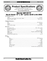
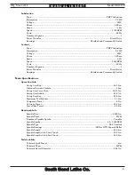
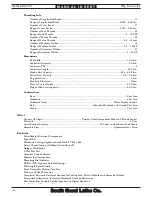
MODEL SB1037F

16" X 40" LATHE 220V w/DRO

Copyright © June, 2011 by South Bend Lathe Co.  

WARNING: No portion of this manual may be reproduced without written approval. 

#BL14237   Printed in USA

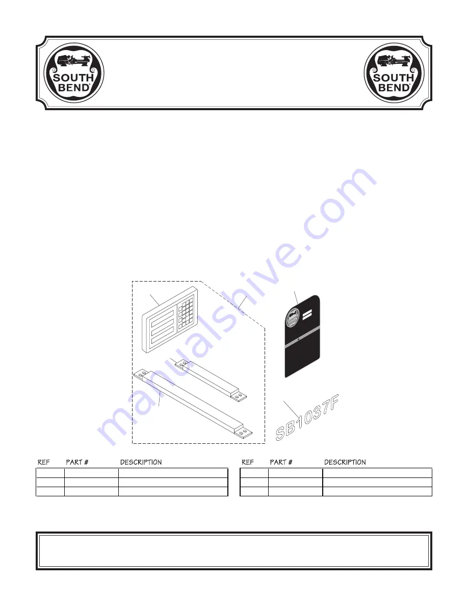
The Model SB1037F Lathe is the same machine as the Model SB1037 except for the following:

•  Added a 2-Axis Fagor Digital Readout (DRO).

Except for the differences noted in this insert, all other content in the Model SB1037 Owner’s Manual 

applies to this machine. Before operating your new lathe, you MUST read and understand this insert, 

the entire Model SB1037 Owner’s Manual, and the Fagor DRO Owner’s Manual to reduce the risk of 

injury when using this machine. Keep this insert for later reference.

If you have any further questions about this manual insert or the differences between the Model 

SB1037F and the Model SB1037, contact our Technical Support at (360) 734-1639 or email 

sales@southbendlathe.com.

REF

PART #

DESCRIPTION

REF

PART #

DESCRIPTION

2318

PSB1037F2318

DRO ASSEMBLY FAGOR 2-AXIS

2318-3

PSB1014F2318-3 DRO Y-AXIS SCALE FAGOR MKT-27

2318-1

PSB1014F2318-1

DRO DISPLAY FAGOR 20-iT

2407

PSB1037F2407

MACHINE ID LABEL

2318-2

PSB1037F2318-2 DRO X-AXIS SCALE FAGOR MKT-102

2416

PSB1037F2416

MODEL NUMBER LABEL

New & Changed Parts

Made 

in T

aiwan 

to South B

end 

Spec

ifica

tions

MODEL SB1037F

16" x 40" EVS 

TOOLR

OOM 

LATHE 

w/DR

O

MFG Date

Serial Nu

mber

TO REDUCE THE RISK OF SERIOUS PERSONA

L INJUR

Y WHILE USING THIS 

MA

CHINE:

  1. 

Read and understand manual bef

ore star

ting

.

  2. 

Always wear appro

ved 

eye protec

tion.

  3. 

Make sur

e the mac

hine is connec

ted to a grounded po

wer sourc

e.

  4. 

Keep all guards in place.

  5. 

DO NO

T wear loose c

lothing

, glo

ves

, or je

welr

y; secur

e long hair and 

roll up long slee

ves

.

  6. 

Disc

onnec

t po

wer bef

ore ser

vice, ma

intenanc

e, or adjustments

.

  7. 

DO NO

T oper

ate when tir

ed or unde

r the influence of

 drugs or alc

ohol.

  8. 

Make sur

e the mac

hine is proper

ly adjuste

d/set up bef

ore star

ting

.

  9. 

Change c

utting fluid r

egular

ly and av

oid c

ontac

t with skin.

 10. 

Make sur

e w

orkpiec

e is pro

per

ly and sec

urely held in the chuc

k and has 

safe c

lear

ance through full rota

tion

 bef

ore star

ting the la

the.

 11. 

Nev

er leav

e the chuc

k ke

y in the 

chuck.

 12. 

Nev

er touch the chuc

k or w

orkpiec

e when it i

s in motion.

 13. 

Nev

er leav

e the la

the running 

una

ttended.

 14. 

Make sur

e long w

orkpieces ar

e prop

erly suppor

ted.

 15. 

Always use the proper 

speed r

ate f

or the ma

terial y

ou ar

e tur

ning

.

 16. 

Do not allo

w c

hildr

en to hav

e unsuper

vised ac

cess to the mac

hine.

WA

RNI

NG

!

!

Motor

: 7.5HP

, 220V

, 3-Ph,

 60Hz

Full

-Load Cur

rent 

Rati

ng: 21.

7A

Swing

 Ov

er Bed: 16.

14"

Dist

ance Between Cent

ers:

 40"

Swing

 ov

er cross

 slide: 10.

375"

Swing

 ov

er ga

p: 22.95"

Spi

ndl

e nose t

o gap (m

ax.): 6.

5"

Cros

s sli

de tr

avel

: 9"

Compound t

rav

el: 5.

1"

Spi

ndl

e Nose:

 D1-6 Camlock

Spi

ndl

e Bor

e: 2-1/16

"

Taper Ins

ide Spi

ndle:

 MT#6

Taper Ins

ide T

ailst

ock: MT#4

Wei

ght:

 3080 lbs

.

2416

2407

2318

2318-1

2318-3

2318-2

Summary of Contents for SB1037F insert

Page 1: ...LROOM LATHE w D RO MF G Da te Serial Nu mb er TO REDUCE THE RISK OF SERIOUS PERSONAL INJURY WHILE USING THIS MACH INE 1 Read and understand manual before starting 2 Always wear approved eye protection...

Page 2: ...5 x 69 in Electrical Power Requirement 220V 3 Phase 60 Hz Full Load Current Rating 21 7A Minimum Circuit Size 30A Inverter Type Yaskawa G7A25P5 Switch Magnetic with Thermal Protection Switch Voltage 2...

Page 3: ...16 14 in Distance Between Centers 40 in Swing Over Cross Slide 10 375 in Swing Over Saddle 15 67 in Swing Over Gap 22 95 in Maximum Tool Bit Size 0 75 in Compound Travel 5 1 in Carriage Travel 38 58 i...

Page 4: ...Headstock Gears Flame Hardened Steel Bed Induction Hardened and Ground Cast Iron Stand Cast Iron Other Country Of Origin Taiwan Some Components Made in USA and Japan Warranty 1 Year Serial Number Loc...

Page 5: ...of Lathes Sold With a Tradition of Quality Since 1906 March 2010 by South Bend Lathe Co For Machines Mfg Since 7 09 14 16 EVS TOOLROOM LATHES MODELS SB1012 SB1014 SB1037 220V MODELS SB1013 SB1015 SB10...

Page 6: ...ess that happens through training and experience If you are not an experienced operator of this type of machinery read through this entire manual then learn more from an experienced operator schooling...

Page 7: ...of Controls Components 24 Main Power Switch 24 Headstock Controls 24 Carriage Controls 24 Control Panel 25 Tailstock Controls 26 Foot Brake 26 Chuck Faceplate Mounting 27 Removing Chuck or Faceplate...

Page 8: ...8 Apron 58 Lead Screw Feedrod Bearings 59 Lead Screw 59 Ways Slides 59 Unpainted Machined Surfaces 59 Ball Oilers 60 Cleaning Electrical Box Filter 60 End Gearing 61 Cutting Fluid System 62 Hazards 62...

Page 9: ...he operator to quickly set the exact spindle speed within the available range of 20 2500 RPM Spindle speed is displayed on a digital readout and controlled within each speed range with the use of a di...

Page 10: ...Cutting Fluid Pump Tank Q Spindle Rotation ON OFF Lever R Half Nut Lever S Apron Oil Level Sight Glass T Quick Change Apron Feed Direction Knob U Manual Way Oil Pump V Brake Pedal W Feed Control Leve...

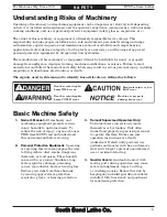
Page 11: ...follows Death or catastrophic harm WILL occur Moderate injury or re MAY occur Death or catastrophic harm COULD occur Machine or property damage may occur Basic Machine Safety 1 Owner s Manual All mach...

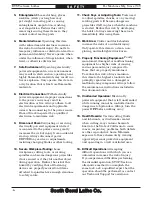
Page 12: ...ing that all fastening devices are properly secured and items attached to spindles have enough clearance to safely rotate 11 Chuck Keys or Adjusting Tools Tools used to adjust spindles chucks or any m...

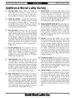
Page 13: ...r risk change cutting fluid regularly and position the cutting fluid nozzle where it will not splash or end up on the floor 1 Clearing Chips Metal chips can easily cut bare skin even through a piece o...

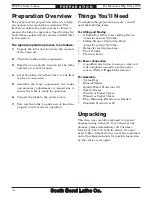
Page 14: ...cover any damage please immediately call Customer Service at 360 734 1540 for advice You may need to file a freight claim so save the containers and all packing materials for possible inspection by th...

Page 15: ...Set 1 5 10mm 1 K Dead Center MT 4 1 L Carbide Tipped Dead Center MT 4 1 M Tapered Spindle Sleeve MT 6 4 1 N Open End Wrench 22 24mm 1 O Open End Wrench 14 17mm 1 P Open End Wrench 10 12mm 1 Q Phillips...

Page 16: ...ts though test them on an inconspicuous area of a painted area to make sure they will not damage it Basic steps for removing rust preventative 1 Put on safety glasses and disposable gloves 2 OAT ALL S...

Page 17: ...ound the machine to open or remove doors covers as required by the maintenance and service described in this manual Physical Environment The physical environment where your machine is operated is impo...

Page 18: ...sk others for help and use power equipment 4 To further balance the load loosen the carriage lock bolt see Figure 6 disengage the half nut lever put the feed control lever in neutral then use the carr...

Page 19: ...ither use the included foot pads and leveling hardware or bolt your lathe to the floor Because mounting your lathe to the floor with permanent hardware is an optional step and floor materials may vary...

Page 20: ...ads Studs Lubricating Lathe GEARBOXES MUST BE FILLED WITH OIL NO OIL SHIPPED WITH MACHINE Refer to the Lubrication Section in this Manual for Recommended Oil Type Bolting to Concrete Floors Lag Screw...

Page 21: ...sult in fire For best results use the shortest length of cord possible for your machine and never use a smaller cord gauge than the specified minimum This machine is equipped with a frequency drive th...

Page 22: ...ain relief to ensure it is properly tightened by pulling the cord from outside the box with light to moderate force When the strain relief is properly tightened the cord will not slide 6 Close and loc...

Page 23: ...ine is controlled by a frequency drive unit constructed with sensitive electronics These electronics can be damaged if power is disconnected during operation Therefore unless the stop button and brake...

Page 24: ...n Pump Switch 6 Turn the spindle speed dial Figure 18 all the way counterclockwise lowest speed to avoid possibility of a high speed start Figure 19 Gearbox range lever in middle position LOW Neutral...

Page 25: ...o you will void the warranty and headstock damage may occur 13 Rotate the stop button Figure 17 on Page 18 clockwise until it pops out The pump will turn ON Observe the oil pump tube sight glass Figur...

Page 26: ...set the stop button by twisting it clockwise until it pops out then restart the spindle with the lever 19 Push the foot brake The lathe should come to a quick stop If the brake pedal has no effect on...

Page 27: ...SE NEUTRAL Spindle Break In It is essential to closely follow the proper break in procedures to ensure trouble free performance Complete this process once you have familiarized yourself with all instr...

Page 28: ...instructions for these adjustments can be found on the pages referenced below Factory adjustments that should be veri ed s 4AILSTOCK ALIGNMENT Page 34 s OMPOUND AND CROSS SLIDE BACKLASH adjustment Pa...

Page 29: ...volution 7 Moves slides to where they will be used during operation 8 If using power feed selects the proper feed rate for the operation 9 Turns the main power switch ON resets the stop button so it p...

Page 30: ...gurations of the gearbox levers to achieve a particular feed rate D Gearbox Levers Move the gearbox gears into particular ratios which then turn the leadscrew and feed rod for threading and power feed...

Page 31: ...and internal components P Quick Change Feed Direction Knob Changes apron feed direction without having to stop the lathe and move the headstock feed direction lever Q Feed Control Lever Engages and di...

Page 32: ...tock offset 1 of 2 AG Offset Scale Indicates the distance of tailstock offset from the spindle center line Figure 37 Tailstock controls AD AA AB AC AE AF AG This lathe is equipped with a foot brake Fi...

Page 33: ...Faceplate 1 DISCONNECT LATHE FROM POWER 2 Lay a chuck cradle see Figure 39 or plywood under the chuck or faceplate and over the bedway to protect the precision ground surfaces from damage and reduce...

Page 34: ...never release 6 Tighten camlocks in a star pattern to draw the chuck up evenly on all sides while reducing chance of alignment and make sure to tighten camlocks in an incremental manner to ensure tha...

Page 35: ...tighten the locking cap screws 5 Make sure that the cam lock studs can rotate back and forth against the head of the locking cap screw see Figure 47 Camlock Stud Can Rotate Back Forth Slightly Cap Scr...

Page 36: ...uck key the jaws move in unison There are two sets of removable hardened steel jaws included with the 3 jaw chuck inside and outside jaws Use the correct jaws for the size and configuration of the wor...

Page 37: ...he chuck key clockwise one turn to engage the tip of the scroll gear lead thread into the jaw Pull on the jaw now it should be locked into the jaw guide 9 Repeat the Steps 6 8 on the remaining jaws Fi...

Page 38: ...t makes contact with the workpiece 6 After the workpiece is held in place by the jaws turn the chuck by hand and pay attention to the workpiece alignment If the workpiece is not correctly aligned for...

Page 39: ...workpiece then re lock the tailstock 4 Start spindle rotation unlock the quill then turn the quill handwheel clockwise to feed the cutting tool into the workpiece Installing Tooling The tailstock quil...

Page 40: ...o your own desired tolerances especially if you have changed the offset to cut shallow tapers To align the tailstock offset to the spindle center line 1 Use a precision level to make sure the bedway i...

Page 41: ...tailstock away from the operator half the distance of the taper Looking down from above Figure 62 Adjust tailstock away from the operator Note As long as this dead center remains in the chuck the poi...

Page 42: ...ters 1 DISCONNECT LATHE FROM POWER 2 Drill center holes in both ends of the workpiece 3 Install the dead center in the spindle and the live center or carbide tipped dead center in the tailstock refer...

Page 43: ...heat that may damage the workpiece Use the dead center in the spindle because the workpiece does not rotate on the tip and does not generate friction Use the carbide tipped dead center in the tailsto...

Page 44: ...heel counterclockwise to draw the quill back into the casting until the center releases To mount a center in the tailstock 1 DISCONNECT LATHE FROM POWER 2 Thoroughly clean and dry the tapered mating s...

Page 45: ...rest supports long shafts and can be mounted anywhere along the length of the bed To install and use the steady rest 1 DISCONNECT LATHE FROM POWER 2 Thoroughly clean the machined base of the steady r...

Page 46: ...he compound slide at a certain angle 1 Loosen the two hex nuts at the base of the compound slide 1 of 2 shown in Figure 71 Compound Slide The four way tool post is mounted on top of the compound slide...

Page 47: ...R stock If the tool is above below the spindle center line a nub will be left in the center of the workpiece Adjust the height of the workpiece then repeat the facing cut to check the adjustment Repea...

Page 48: ...loosen the stop collar so it slides freely on the feedrod Carriage Stop The carriage stop on this lathe will NOT automatically stop the carriage or disengage the power feed Failure to heed this notic...

Page 49: ...peed is important for safe and satisfactory results as well as maximizing tool life To set the spindle speed for your operation you will need to 1 Determine the best spindle speed for the cutting task...

Page 50: ...le speed dial to carefully adjust the spindle speed shown on the digital display to your calculated spindle speed 3 Adjust the spindle speed range lever to the range that covers your calculated spindl...

Page 51: ...ion will now be reversed causing the engaged carriage or cross slide to move in the opposite direction 3 Use the feed control lever on the front of the apron to engage power feed for either the carria...

Page 52: ...HBT4V 2 HBT3V 2 HBT2V 2 HBT1V 3 HCT6Z 4 HCS1Z 5 HCS3Z 6 HCS6Z 7 HCS8Z 8 HCR1Z 9 HCR2Z 1 0 HCR3Z 1 25 HCS3Y 1 5 HCS6Y 1 75 HCS8Y 2 0 HCR1Y 2 25 HCR2Y 2 5 HCR3Y 2 75 HCR4Y 3 0 HCR6Y 3 25 HCR7Y 3 5 HCR8Y...

Page 53: ...installed in the top position the 44T 56T end gears in the middle position and the 57T end gear in the bottom position as shown in Figure 86 In the normal position the 56T and 57T gears are meshed wh...

Page 54: ...rash Figure 90 Feed control lever and half nut positions for threading Threading Controls If you are unfamiliar with how to cut threads on a lathe we strongly recommend that you read books review indu...

Page 55: ...ples explain how to use the thread dial chart TPI 4 72 Divisible By 4 Use any line position on the thread dial shown in Figure 93 for threading TPI divisible by four Figure 93 Any position on the dial...

Page 56: ...and more than half of the way the drawer could fall out and hit your feet causing serious injury Therefore open the drawer slowly and avoid opening it more than half of the way Figure 99 Chip drawer...

Page 57: ...hazard X X X X X X X X X X X X X X X X X X X X Aluminum Brass Bronze Cast iron Low Carbon Steel Alloy Metals Stainless Steel General Note Cutting fluids are used for heavy duty lathe operations and pr...

Page 58: ...s PPLICABLE FOR LATHES AND HIGH SPEED turning s 7ATERPROOF DESIGN s CENTERS SB1266 8 Backplate D1 6 for SB1012 SB1013 Lathes SB1267 10 Backplate D1 6 for SB1014 SB1015 SB1037 SB1038 Lathes High Precis...

Page 59: ...antique finished frame They are easy to read from a distance and measure 14 in diameter Pictures just don t do them justice They are very nice quality clocks and perfect for the South Bend Lathe afici...

Page 60: ...THE POWER FEED LEVER ON THE APRON TO neutral to prevent crashes upon startup s NSURE CARRIAGE LOCK BOLT IS LOOSE Daily During Operations s 6ERIFY HEADSTOCK OIL mOWS WHEN POWER IS turned ON Page 56 s 6...

Page 61: ...s Keep track of when you last performed your annual service and when you ll need to perform it again Make copies of this page to use each month Keep each chart as a maintenance record for your South B...

Page 62: ...eadstock oil tank components Sight Glass Headstock Oil Tank Oil Fill Spout Monitoring Oil Temperature During operations regularly monitor the oil temperature shown in the sight glass in Figure 109 The...

Page 63: ...for fumes 7 Using mineral spirits and rags wipe down the inside of the tank to clean it Make sure to soak up any excess mineral spirits with a dry rag so it does not stay in the tank Figure 110 Heads...

Page 64: ...or extreme working conditions Figure 113 shows fill and drain plugs used when changing the gearbox oil Apron Oil Type Mobil Vactra 2 or ISO 68 Equivalent Oil Amount 1 Liter Check Add Frequency Daily C...

Page 65: ...of the way so you can clean the entire length of the leadscrew Apply oil along the length of the leadscrew Use a paint brush to make sure the oil is evenly applied and down in the threads Lead Screw F...

Page 66: ...Box Filter The door of the electrical box contains an air filter Figure 120 to prevent dust from entering the box as the cooling fan pulls in cool air to reduce heat The air filter should be cleaned...

Page 67: ...cover and all the end gears shown in Figure 121 3 Clean the end gears thoroughly with mineral spirits to remove all the old grease Use a small brush if necessary to clean between the teeth 4 Clean the...

Page 68: ...hown in Figure 123 Figure 123 Cutting fluid pump and tank Tank Pump Motor Although most swarf from machining operations falls into the chip tray and stays there some small chips drain into the tank Th...

Page 69: ...permanently damage it This is abuse and not covered by the warranty Note The electrical conduit was purposely left long so the tank can be removed without disconnecting wires from the pump Do not disc...

Page 70: ...ng temperature then drain and refill the all gearboxes with fresh oil Note During extended storage more than two years any component above the oil level may rust from condensation We recommend overfil...

Page 71: ...Compound slide backlash adjustment set screws Set Screws Compound Leadscrew Tools Needed Qty Hex Wrench 3mm 1 Backlash is adjusted by tightening the set screws shown in Figure 125 When these screws a...

Page 72: ...and held in position by a screw at each end To adjust the gib turn one screw a 1 4 turn clockwise and the other screw a 1 4 turn counterclockwise so both screws move toward the same direction Now test...

Page 73: ...ib adjustment Leadscrew Half Nut Adjustment Set Screws Thread Dial Removed Half Nut Right Gib Screw Figure 131 One of two tailstock gib screws 4 Engage disengage the half nut several times and notice...

Page 74: ...hole in the clutch collar with the closest set screw slot that is cut into the feedrod see Figure 135 6 Install and tighten the set screw so it is fully seated in the slot 7 Re install both access co...

Page 75: ...tor and eye protection to protect yourself from hazardous brake dust 3 Remove the motor cover shown in Figure 137 4 Measure the remaining brake band lining at the thinnest point which is usually at th...

Page 76: ...ll switch shown in Figure 141 at the tailstock end of the lathe 11 Push the pedal lever down to verify that the cam lobe pushes the kill switch plunger in When pushed in the switch should click If the...

Page 77: ...eed access covers as shown in Figure 143 3 Rotate the shroud washer so the cutout lines up with the shear pin head as shown in Figure 144 Figure 145 Shear pin access Rear Position Gap 4 Put on safety...

Page 78: ...d then rotate the lathe spindle to line up the inner and outer bores as shown in Figure 146 Next use the magnet to remove the other half of the broken shear pin when it becomes visible 11 Using retain...

Page 79: ...ting surfaces 3 Place the gap insert into the gap and use a block of wood or dead blow hammer to align the insert with the lathe bed 4 Back off the dowel pin jack nuts and tap the dowel pins back into...

Page 80: ...relay cut out dial to increase working amps and push the reset pin Replace if tripped multiple times weak relay 9 Motor connection wired incorrectly 9 Correct motor wiring connections 10 Oil pump moto...

Page 81: ...m tailstock quill 1 Quill is not retracted all the way back into the tailstock 1 Turn the quill handwheel until it forces taper out of quill 2 Contaminants not removed from taper before inserting into...

Page 82: ...sh button is engaged or at fault 2 Rotate button clockwise until it pops out to reset it for operation replace if not working properly 3 Power supply is switched OFF at main power switch or breaker 3...

Page 83: ...his machine complies with the provisions of any law act code regulation or standard of any domestic or foreign government industry or authority In no event shall South Bend s liability under this warr...

Page 84: ...South Bend Lathe Co P O Box 2027 Bellingham WA 98227 PHONE 360 734 1540 Administrative Of ces FAX 360 676 1075 International FAX 360 734 1639 USA only southbendlathe com Printed In Taiwan BLTRCR12117...

Page 85: ...of Thousands of Lathes Sold With a Tradition of Quality Since 1906 March 2010 by South Bend Lathe Co For Machines Mfg Since 7 09 16 X 40 EVS TOOLROOM LATHES MODEL SB1037 220V MODEL SB1038 440V SPECIF...

Page 86: ...Circuit Size 30 Amp Plug Included No Recommended Plug Type L15 30 Motors Main Type TEFC Induction Horsepower 71 2 HP Voltage 220V Phase 3 Phase Amps 20A Speed 0 4500 RPM Cycle 60 Hz Number Of Speeds V...

Page 87: ...e Taper MT 6 Number of Spindle Speeds Variable Range of Spindle Speeds 20 2500 RPM Spindle Type D1 6 Camlock Spindle Bearings NSK or NTN Tapered Roller Spindle Length 24 24 Spindle Length with 3 Jaw C...

Page 88: ...eter Carriage Stop Threading Dial Indicator NSK or NTN Japanese Spindle Bearings Full Length Splash Guard Front Removable Sliding Chip Tray Yaskawa G7A25P5 Inverter Completely Enclosed Universal Gearb...

Page 89: ...o Recommended Plug Type Hardwire to Locking Disconnect Switch Motors Main Type TEFC Induction Horsepower 71 2 HP Voltage 440V Phase 3 Phase Amps 10A Speed 0 4500 RPM Cycle 60 Hz Number Of Speeds Varia...

Page 90: ...le Taper MT 6 Number of Spindle Speeds Variable Range of Spindle Speeds 20 2500 RPM Spindle Type D1 6 Camlock Spindle Bearings NSK or NTN Tapered Roller Spindle Length 24 24 Spindle Length with 3 Jaw...

Page 91: ...eter Carriage Stop Threading Dial Indicator NSK or NTN Japanese Spindle Bearings Full Length Splash Guard Front Removable Sliding Chip Tray Yaskawa G7A25P5 Inverter Completely Enclosed Universal Gearb...

Page 92: ...outh Bend Lathe Co P O Box 2027 Bellingham WA 98227 PHONE 360 734 1540 Administrative Offices FAX 360 676 1075 International FAX 360 734 1639 USA only southbendlathe com Printed In Taiwan BL12164 1216...

Page 93: ...f Lathes Sold With a Tradition of Quality Since 1906 November 2009 by South Bend Lathe Co For Machines Mfg Since 7 09 14 16 EVS TOOLROOM LATHES MODELS SB1012 SB1014 SB1037 220V MODELS SB1013 SB1015 SB...

Page 94: ...you do not have experience working with electricity or performing wiring tasks we strongly encourage you to get help from an experienced individual such as an electrician or from our technical support...

Page 95: ...ble results including serious injury or re 4 Motor Wiring The motor wiring shown in these diagrams is current at the time of printing but it may not match your machine Always use the wiring diagram in...

Page 96: ...9 Coolant Pump Motor Page 11 Oil Pump Motor Page 10 Oil Pressure Switch Page 10 Door Limit Switch Page 14 Brake Limit Switch Page 14 Spindle Switch Page 13 Spindle RPM Sensor Page 14 Chuck Guard Limi...

Page 97: ...e Limit Switch Page 14 Chuck Guard Limit Switch Page 14 Electrical Box Pages 6 7 Cooling Fan Page 6 Main Power Switch Page 6 Control Panel Page 12 Work Lamp Page 14 Work Lamp Page 14 Component Locatio...

Page 98: ...5 A1 9 6 7 8 5 4 0 0 CONTACTOR Allen Bradley C09 400 1 3 5 7 L1 L2 A1 A2 A1 A2 L3 L4 1 3 5 7 L1 L2 L3 L4 2 4 6 8 T1 2 T1 T2 4 T2 T3 6 T3 2 T1 4 T2 6 T3 T4 2 4 6 8 T1 T2 T3 T4 95 96 NO NC 97 98 95 96...

Page 99: ...d N6H 6L6 VARIABLE SPEED UNIT REFER TO YASKAWA OWNERS MANUAL Main Junction Block Ground 11 10 L11 L13 U1 V1 W1 U2 V2 W2 U V W 0 0 1 1 2 2 3 3 4 5 6 7 8 9 K L 11 COM L11 L13 A1 16 15 17 L1 L2 L3 B1 B2...

Page 100: ...6 For Machines Mfg Since 8 09 EVS Toolroom Lathes E L E C T R I C A L Fig 2 Electrical box Electrical Box box photo...

Page 101: ...Z VcY ejbe bdidg Figure 3 Spindle motor location Figure 4 Spindle motor location SPINDLE MOTOR 220V Ground W Bk Bk U1 U5 V1 V5 W5 W1 V6 V2 U2 W6 U6 W2 V U Yl To Electrical Box Page 7 SPINDLE MOTOR 440...

Page 102: ...ressure sensor location Oil Pump Motor Oil Pump Motor Oil Pressure Sensor and Pump Ground OIL PUMP MOTOR 220V V2 W2 U2 U1 U5 V1 V5 W5 W1 U2 U2 V2 W2 To Electrical Box Page 7 Ground OIL PUMP MOTOR 440V...

Page 103: ...TOR 220V 3 2 1 4 6 5 W1 W1 V1 V1 U1 Ground COOLANT PUMP MOTOR 440V Ground 3 2 1 4 6 5 W1 W1 V1 V1 U1 220V Coolant Pump Wiring 440V Coolant Pump Wiring Figure 7 Coolant pump location Figure 8 Coolant p...

Page 104: ...220V GND IN 12V 110V 0V Bk X X 13 X 14 COM L K L11 1 3 3 TACHOMETER DISPLAY SPINDLE SPEED DIAL COOLANT PUMP SWITCH JOG BUTTON POWER LAMP EMERGENCY STOP BUTTON 1 2 3 X1 X2 4 4 3 3 2 1 20 L13 2 3 12 4 1...

Page 105: ...ndle Rotation Switch Figure 10 spindle rotation and power conn tection Ground Hot Hot Hot 15 20 PLUG as recommended L3 L2 L1 1 2 3 5 6 4 MASTER POWER SWITCH L3 L3 L2 L2 L1 L1 Ground Hot Hot Hot DISCON...

Page 106: ...COMMON NC NO Bk Wt X K COM L A1 3 X 1 0 Bk Wt 0 2 13 14 21 22 NC NC NO NO 3 4 X 5 A1 X 9 Door Limit Switch Figure 11 Work Light Brake Limit Switch Figure 12 Spindle RPM Sensor Figure 11 Chuck Guard L...

Page 107: ...ine complies with the provisions of any law act code regulation or standard of any domestic or foreign government industry or authority In no event shall South Bend s liability under this warranty exc...

Page 108: ...South Bend Lathe Co P O Box 2027 Bellingham WA 98227 PHONE 360 734 1540 Administrative Of ces FAX 360 676 1075 International FAX 360 734 1639 USA only southbendlathe com Printed In Taiwan JB12236...

Page 109: ...of Lathes Sold With a Tradition of Quality Since 1906 November 2009 by South Bend Lathe Co Revised February 2010 TS For Machines Mfg Since 7 09 16 X 40 EVS TOOLROOM LATHES MODEL SB1037 220V MODEL SB1...

Page 110: ...le for purchase and some individual parts may only be available in assemblies with other parts In the case of fasteners or other off the shelf hardware we will happily provide customers with replaceme...

Page 111: ...12 Apron Rear View 14 Dial Indicator 16 Carriage Stop 16 Compound Slide Tool Post 17 Saddle Body Controls 18 Saddle Base 20 Bed Shafts 21 End Gears 23 Motor Assembly 24 Cabinets Panels 26 Headstock O...

Page 112: ...CR M5 8 X 8 2 PCAP29M CAP SCREW M6 1 X 40 9 PSB10120009 OIL DISTRIBUTOR A 5S 3 PSB10120003 HEADSTOCK COVER 9 1 PSB10120009 1 OIL DISTRIBUTOR BRACKET 4 PSB10120004 COVER OIL SEAL M4 X 1700 10 PSB101200...

Page 113: ...1038 Parts 3 P A R T S Headstock Controls 14 15 16 17 18 19 20 21 22 23 24 25 26 27 28 29 30 31 32 33 34 35 36 37 38 39 40 41 42 43 44 45 46 47 48 49 50 14 15 16 17 18 19 20 21 21 30 33 34 37 38 39 21...

Page 114: ...20 PSB10120020 HEADSTOCK CASTING PLUG 18MM 39 PEC015M E CLIP 8MM 21 PORP021 O RING 20 8 X 2 4 P21 40 PK12M KEY 5 X 5 X 30 22 PSB10120022 SHIFT CAM 41 PSB10120041 SHIFT ROD 23 PR03M EXT RETAINING RING...

Page 115: ...el SB1037 SB1038 Parts 5 P A R T S Headstock Upper Gearing 55 56 57 58 59 60 61 62 63 64 65 66 67 68 69 70 71 72 73 74 75 76 77 78 79 80 81 82 83 84 85 86 87 88 89 90 91 92 93 94 95 96 97 98 99 100 60...

Page 116: ...38T 87 PK28M KEY 7 X 7 X 30 64 PSB10120064 DRIVE SHAFT 88 PCAP48M CAP SCREW M6 1 X 35 65 PK27M KEY 7 X 7 X 25 89 PSB10120089 FRONT SPINDLE BEARING COVER 66 PR15M EXT RETAINING RING 30MM 90 PSB10120090...

Page 117: ...OUBLED ENDED GEAR 12T 21T 106 PSB10120106 GEAR 21T 119 PSB10120119 GEAR SHAFT 107 PSB10120107 GEAR 42T 120 PSB10120120 GEAR 21T 108 PK99M KEY 6 X 6 X 15 121 PSB10120121 SPLINE SHAFT SPACER 109 PR12M E...

Page 118: ...207 208 209 210 211 212 213 214 215 216 217 218 219 220 221 222 223 224 225 226 227 228 229 230 231 232 233 234 235 236 237 238 239 240 241 242 243 244 245 246 247 248 249 250 251 252 253 254 255 256...

Page 119: ...4 PSB10120214 GEAR SPACER 245 PSB10120245 GEAR 22T 215 PR11M EXT RETAINING RING 25MM 246 PSB10120246 GEAR 22T 216 PSB10120216 SPLINE SHAFT 247 PSB10120247 GEAR 33T 217 PSB10120217 SPLINE SHAFT 248 PSB...

Page 120: ...273 274 275 276 277 278 279 280 281 282 283 284 285 286 287 288 289 290 291 292 293 294 295 296 297 298 299 300 301 302 303 304 305 306 307 308 309 310 311 312 313 314 315 316 317 318 319 320 321 322...

Page 121: ...PSB10120278 LOWER FORK 317 PSB10120317 SELECTOR LEVER END CAP 279 PSB10120279 MIDDLE FORK 318 PSB10120318 SELECTOR PLATE 280 PSB10120277 UPPER FORK 319 PSB10120319 SHIFTING HANDLE 281 PRP02M ROLL PIN...

Page 122: ...Apron Front View 501 502 503 504 505 506 507 508 509 510 511 512 513 514 515 516 517 518 519 520 521 522 523 524 525 526 527 528 529 530 531 532 534 535 537 538 539 540 541 542 544 545 546 547 548 549...

Page 123: ...2 PSB10120512 FEED CONTROL HANDLE 542 PSB10120542 INCH INDEX RING 513 PSB10120513 FEED CONTROL WORM 544 PSB10120515 COMPRESSION SPRING 6 X 16 514 PSTB001 STEEL BALL 1 4 545 PSB10120545 HANDWHEEL 515 P...

Page 124: ...ce 8 09 Model SB1037 SB1038 Parts P A R T S Apron Rear View 514 522 534 550 551 552 553 554 555 556 558 559 561 562 563 565 566 567 568 569 570 572 573 574 575 576 577 578 579 580 581 582 583 611 612...

Page 125: ...0576 STEP PIN 554 PSB10120554 NEEDLE BEARING NK29 30 577 PSB10120577 PIVOT LEVER 555 PSB10120555 BEARING SPACER 578 PSB10120578 RETAINING BLOCK 556 PR11M EXT RETAINING RING 25MM 579 PSB10120579 INCH H...

Page 126: ...CAP SCREW M6 1 X 10 753 PSS02M SET SCREW M6 1 X 6 754 PN03M HEX NUT M8 1 25 Carriage Stop 801 802 803 804 805 806 807 808 809 810 811 812 REF PART DESCRIPTION 801 PCAP71M CAP SCREW M10 1 5 X 60 802 P...

Page 127: ...T BOLT KEY 908 PSB10120908 COMPRESSION SPRING 6 X 27 951 PCAP01M CAP SCREW M6 1 X 16 909 PSB10120909 TOOL POST BASE 952 PSS04M SET SCREW M6 1 X 12 910 PSB10120910 COMPOUND SLIDE 953 PCAP26M CAP SCREW...

Page 128: ...004 1005 1006 1007 1008 1009 1010 1013A 1014 1015 1016 1017 1018 1019 1022 1023 1024 1025 1026 1027 1028 1029 1030 1031 1032 1033 1034 1035 1036 1037 1038 1039 1040 1051 1101 1102 1103 1104 1105 1106...

Page 129: ...3A PSB10121013A CROSS LEADSCREW W NUT ASSY 1051 PSB10121051 SADDLE OIL PUMP ASSEMBLY 1014 PK165M KEY 3 X 3 X 100 1101 PLUBE001 TAP IN BALL OILER 1 4 1015 PRP28M ROLL PIN 5 X 40 1102 PSS28M SET SCREW M...

Page 130: ...0121044 STRAIGHT PIPE ADAPTER 1 8 PT X 4MM 1106 PS08M PHLP HD SCR M5 8 X 12 1045 PSB10121045 ALUMINUM TUBE 4 X 260MM 1111 PSS03M SET SCREW M6 1 X 8 1046 PSB10121046 ELBOW ADAPTER 1 8 PT X 4MM 1113 PCA...

Page 131: ...1204 1205 1206 1207 1208 1209 1210 1211 1212 1213 1214 1215 1216 1217 1218 1219 1220 1221 1222 1223A 1225 1226 1227 1228 1229 1230 1232 1234 1235 1236 1237 1301 1302 1303 1304 1305 1306 1307 1308 130...

Page 132: ...E ROD LEVER 1304 PSS30M SET SCREW M10 1 5 X 10 1213 PSB10121213 SPINDLE ROD LEVER KNOB 1305 PCAP128M CAP SCREW M8 1 25 X 70 1214 PSB10121214 SPINDLE LEVER HUB BRACKET 1306 PSB10121306 TAPER PIN 7 X 3...

Page 133: ...PSB10141404 PIVOT ARM 1414 PK28M KEY 7 X 7 X 30 1405 PK166M KEY 7 X 7 X 15 1415 PSB10121415 PIVOT ARM STUD 1406 PN32M HEX NUT M14 2 1416 PCAP14M CAP SCREW M8 1 25 X 20 1407 PSB10121407 GEAR WASHER 14...

Page 134: ...embly 1501 1504 1505 1506 1507 1508 1509 1510 1511 1512 1513 1514 1515 1516 1517 1518 1519 1519 1 1519 2 1519 3 1520 1521 1522 1523 1524 1525 1526 1527 1528 1529 1530 1531 1532 1533 1534 1535 1536 153...

Page 135: ...CAP SCREW M8 1 25 X 55 1509 PSB10121509 MOTOR PULLEY 1527 PSB10121527 MOUNTING INSERT 1510 PCAP01M CAP SCREW M6 1 X 16 1528 PSB10121528 MOTOR MOUNTING 10T 395 X 300MM 1511 PSB10121511 TAPER PIN 4 X 1...

Page 136: ...3 1604 1605 1606 1608 1609 1610 1611 1612 1613 1614 1616 1617 1618 1619 1620 1621 1622 1623 1624 1625 1626 1627 1628 1629 1630 1631 1632 1633 1634 1635 1636 1637 1638 1639 1640 1642 1643 1644 1645 164...

Page 137: ...SB10121613 CHIP TRAY L BRACKET 1640 PSS34M SET SCREW M5 8 X 16 1614 PW04M FLAT WASHER 10MM 1642 PN03M HEX NUT M8 1 25 1616 PSB10121616 LEFT CABINET 1643 PSB10121643 SPLASH GUARD 1617 PSB10121617 LEFT...

Page 138: ...dstock Oiling System A B C D E A B C D E 1701 1704 1705 1706 1707 1708 1709 1710 1711 1712 1713 1714 1715 1716 1717 1718 1719 1720 1721 1722 1723 1724 1725 3 1726 1727 1728 1729 1730 1731 1732 1733 17...

Page 139: ...1727 PSB10121727 RUBBER RING 3 8 1711 PSB10121711 MINOR TIP 1728 PSB10121728 STAND PIPE 3 8 PT X 8 1712 PRP02M ROLL PIN 3 X 16 1729 PSB10121729 NYLON OIL DELIVERY TUBE 10 X 100MM 1713 PSB10121713 SPI...

Page 140: ...2 1803 1804 1805 1806 1807 1808 1809 1810 1811 1812 1813 1814 1815 1816 1817 1818 1819 1821 1822 1823 1824 1825 1826 1827 1828 1829 1830 1831 1832 1833 1834 1837 1838 1839 1840 1901 1902 1903 1904 190...

Page 141: ...1 25 X 90 1840 PSB10121840 TAILSTOCK STUD M14 2 X 110 1812 PSB10121812 HANDWHEEL HANDLE 1901 PCAP01M CAP SCREW M6 1 X 16 1813 PSB10120515 COMPRESSION SPRING 6 X 16 1902 PSS04M SET SCREW M6 1 X 12 181...

Page 142: ...2011 PSB10122011 CLAMP STUD DOWEL PIN 2012 PSB10142012 TOP STEADY REST CASTING 2012A PSB10142012A STEADY REST ASSEMBLY 2013 PSB10142013 BOTTOM STEADY REST CASTING 2014 PSB10122014 HINGE PIN 2015 PSB10...

Page 143: ...el SB1037 SB1038 Parts 33 P A R T S Electrical Cabinet Control Panel 2201 2202 2203 2204 2205 2206 2208 2209 2210 2211 2212 2213 2214 2215 2217 2218 2219 2220 2221 2222 2223 2224 2225 2226 Electrical...

Page 144: ...MAIN POWER SWITCH 2218 PSB10122218 SPINDLE SPEED DIAL 2206 PSB10142206 INVERTER YASKAWA CIMR G7A25P5 SB1037 2219 PSB10122219 POWER LAMP 2206 PSB10152206 INVERTER YASKAWA CIMR G7A45P5 SB1038 2220 PSB1...

Page 145: ...HUCK JAW SET 2309 PSB10122309 SPINDLE SLEEVE MT 4 MT 6 2301 3 PSB10122301 3 4 JAW CHUCK CAMLOCK STUD SET 2310 PSB10122310 3 JAW CHUCK REVERSIBLE JAW SET 2302 PSB10122302 3 JAW CHUCK 8 ASSEMBLY 2311 PW...

Page 146: ...07 PSB10372407 MACHINE ID LABEL SB1037 2416 PSB10372416 MODEL NUMBER LABEL SB1037 2407 PSB10382407 MACHINE ID LABEL SB1038 2416 PSB10382416 MODEL NUMBER LABEL SB1038 2408 PSB10122408 CHANGING SPEED NO...

Page 147: ...DESCRIPTION REF PART DESCRIPTION 2419 PSBLABEL01HS DISCONNECT POWER LABEL 2423 PSB10122423 220V 3 PHASE LABEL SB1037 2420 PSBLABEL15M ELECTRICITY LABEL 2423 PSB10132423 440V 3 PHASE LABEL SB1038 2421...

Page 148: ...South Bend Lathe Co P O Box 2027 Bellingham WA 98227 PHONE 360 734 1540 Administrative Offices FAX 360 676 1075 International FAX 360 734 1639 USA only southbendlathe com Printed In Taiwan TS12318...

Reviews: