South Bend Tools
For Machines Mfd. Since 12/20
Model SB1117
-29-
O P E R A T I O N
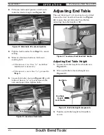
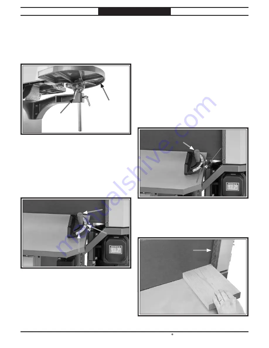
Adjusting End Table Tilt
1.
Loosen end table tilt lock handle (see
Figure 42).
2.
Tilt end table to desired angle (see
Figure 42).
3.
Tighten end table tilt lock handle to secure.
Figure
Figure 42. End table tilt components.
. End table tilt components.
End Table
End Table
End Table Tilt
End Table Tilt
Lock Handle
Lock Handle
Adjusting Miter Stop
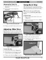
The main table has a stationary miter stop (see
Figure 43) that is used to support the workpiece
at various angles against the sanding belt.
Figure
Figure 43. Main table miter stop.
. Main table miter stop.
Lock
Lock
Handle
Handle
Pointer
Pointer
Scale
Scale
To use back stop:
1.
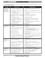
Remove lock handle and flat washer shown
in Figure 44.
2.
Remove scale pointer knob shown in Figure
44 to remove pointer.
Scale Pointer
Scale Pointer
Knob
Knob
Pointer
Pointer
Figure
Figure 44. Miter stop removal components.
. Miter stop removal components.
Lock Handle &
Lock Handle &
Flat Washer
Flat Washer
Using Back Stop
When mitered support is not needed, the miter
stop can be removed so workpieces can be instead
supported by the back stop and the main table.
Note
: Use these steps to re-install the miter
stop and be sure to calibrate the scale before
use by referring to Calibrating Miter Stop on
Page 35.
3.
Remove miter stop body from table.
4.
Use back stop to support workpieces, as
shown in Figure 45.
To adjust miter stop:
1.
Loosen lock handle shown in Figure 43.
2.
Rotate miter stop to until pointer on scale
indicates desired angle (see Figure 43).
3.
Tighten lock handle from Step 1 to secure.
Figure
Figure 45. Workpiece supported by back stop.
. Workpiece supported by back stop.
Back Stop
Back Stop


