background image

-110-

For Machines Mfg. Since 3/11

Turn-Nado

®

 Gearhead Lathes

P A R T S

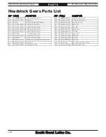
Gearbox Parts List

REF PART #

DESCRIPTION

REF PART #

DESCRIPTION

403

PSB1046PF0403 SELECTOR LEVER PIN

418

PSB1046PF0418

SHIFT FORK

404

PSB1046PF0404 LEVER CAP

419

PCAP02M

CAP SCREW M6-1 X 20

405

PSB1046PF0405 LEVER RETAINING FLAT WASHER

420

PRP24M

ROLL PIN 5 X 16

406

PSB1046PF0406 SHIFT LEVER

421

PW03M

FLAT WASHER 6MM

407

PSB1046PF0407 SIGHT GLASS

422

PSS02M

SET SCREW M6-1 X 6

408

PSB1046PF0408 GEARBOX COVER (SB1046PF-48PF)

423

PRP04M

ROLL PIN 4 X 24

408

PSB1056F0408

GEARBOX COVER (SB1056F-58F)

424

PSB1046PF0424 SHIFT TAB

409

PSB1046PF0409 COUPLER 3/4" NPT

425

PSB1046PF0425 SHIFT FORK

410

PSB1046PF0410

ELBOW 3/4" NPT

426

PSB1046PF0426 SQUARE HEAD PLUG 1/2" NPT

411

PSB1046PF0411

OIL FILL PLUG 3/4" NPT

427

PSB1046PF0427

PIPE ELBOW 1/2" NPT

412

PK05M

KEY 4 X 4 X 10

428

PSB1046PF0428 COUPLER 1/2" NPT

413

PSB1046PF0413

SELECTOR SHAFT

429

PCAP26M

CAP SCREW M6-1 X 12

414

PSB1046PF0414

SELECTOR BAR

430

PCAP29M

CAP SCREW M6-1 X 40

415

PSB1046PF0415

SHIFT KNUCKLE

431

PCAP38M

CAP SCREW M5-.8 X 25

416

PSB1046PF0416

COMPRESSION SPRING

432

PCAP01M

CAP SCREW M6-1 X 16

417

PSS20M

SET SCREW M8-1.25 X 8

Summary of Contents for TURN-NADO SB10146PF

Page 1: ...lity Since 1906 August 2011 by South Bend Lathe Co For Machines Mfg Since 3 11 TURN NADO GEARHEAD LATHE w DRO MODEL SB1046PF 21 X 60 MODEL SB1056F 18 X 40 MODEL SB1047PF 21 X 80 MODEL SB1057F 18 X 60...

Page 2: ...ocess that happens through training and experience If you are not an experienced operator of this type of machinery read through this entire manual then learn more from an experienced operator schooli...

Page 3: ...ssembly 29 Lubricating Lathe 30 Adding Coolant 30 Power Connection 30 Test Run 32 Spindle Break In 35 Recommended Adjustments 35 OPERATION 36 Operation Overview 36 Chuck Faceplate Mounting 37 Installa...

Page 4: ...77 Leadscrew End Play Adjustment 78 Gib Adjustment 78 Half Nut Adjustment 80 V Belts 80 Spindle Clutch Adjustment 81 Leadscrew Shear Pin Replacement 84 Gap Insert Removal Installation 86 Gap Removal 8...

Page 5: ...bilities These Turn Nado Gearhead Lathes are built for daily use in a busy industrial setting Loaded with many nice features and high precision parts these lathes excel at making fine tools dies threa...

Page 6: ...Safety Switch E Follow Rest F 4 Way Tool Post G Halogen Work Lamp H Steady Rest I Coolant Nozzle Valve J Fagor DRO Control Panel Serious personal injury could occur if you connect the machine to power...

Page 7: ...ing the master power switch to OFF is not a safe alternative to completely disconnecting the machine from power when wiring servicing or making repairs Headstock A Quick Change Gearbox Levers Controls...

Page 8: ...he workpiece O Coolant Flow Control Lever Controls the flow of coolant from the nozzle P One Shot Oiler Draws oil from the apron reservoir to lubricate the carriage ways through various oil ports Q Ha...

Page 9: ...to control tailstock offset accuracy AD Tailstock Offset Screws Adjust the tailstock offset left or right from the spindle centerline Figure 7 Tailstock controls Y Z AA AB AC AD Y Quill The quill has...

Page 10: ...e Figure 9 to quickly stop the spindle instead of allowing it to coast to a stop on its own Pressing the foot brake disengages the spindle clutch from the motor drive train inside the headstock After...

Page 11: ...d Slat Crate Weight 6182 lbs 7040 lbs 8712 lbs Width side to side Depth front to back Height 121 x 45 x 69 141 x 45 x 69 183 x 45 x 69 Electrical Power Requirement 440V 3 Phase 60Hz Full Load Current...

Page 12: ...Permanently Sealed Coolant Motor Type TEFC Induction Horsepower 1 8 HP Voltage 440V Phase 3 Phase Amps 0 23A Speed 3450 RPM Cycle 60 Hz Power Transfer Direct Drive Bearings Shielded Permanently Sealed...

Page 13: ...Feeds 15 Range of Longitudinal Feeds 0 0015 0 0400 in rev Number of Cross Feeds 15 Range of Cross Feeds 0 00075 0 0200 in rev Number of Inch Threads 38 Range of Inch Threads 2 72 TPI Number of Metric...

Page 14: ...adstock Cast Iron Headstock Gears Flame Hardened Steel Bed Meehanite Castings with Induction Hardened Ways Stand Cast Iron Paint Urethane Other Country of Origin Taiwan Some Components Made in USA Ger...

Page 15: ...od Slat Crate Weight 4708 lbs 5522 lbs 6380 lbs Width side to side Depth front to back Height 100 x 45 x 69 121 x 45 x 69 141 x 45 x 69 Electrical Power Requirement 440V 3 Phase 60Hz Full Load Current...

Page 16: ...rmanently Sealed Coolant Motor Type TEFC Induction Horsepower 1 8 HP Voltage 440V Phase 3 Phase Amps 0 23A Speed 3450 RPM Cycle 60 Hz Power Transfer Direct Drive Bearings Shielded Permanently Sealed O...

Page 17: ...of Longitudinal Feeds 0 0015 0 0400 in rev Number of Cross Feeds 15 Range of Cross Feeds 0 00075 0 0200 in rev Number of Inch Threads 38 Range of Inch Threads 2 72 TPI Number of Metric Threads 40 Ran...

Page 18: ...dstock Cast Iron Headstock Gears Flame Hardened Steel Bed Meehanite Castings with Induction Hardened Ways Stand Cast Iron Paint Urethane Other Country of Origin Taiwan Some Components Made in USA Germ...

Page 19: ...as follows Death or catastrophic harm WILL occur Moderate injury or fire MAY occur Death or catastrophic harm COULD occur Machine or property damage may occur Basic Machine Safety Owner s Manual All m...

Page 20: ...by verifying that all fastening devices are properly secured and items attached to spindles have enough clearance to safely rotate Chuck Keys or Adjusting Tools Tools used to adjust spindles chucks or...

Page 21: ...ob and make sure it is sharp A correct sharp tool decreases strain and provides a better finish Speed Rates Operating the lathe at the wrong speed can cause nearby parts to break or the workpiece to c...

Page 22: ...ith deadly force To reduce the risk of this hazard read and understand this document and seek additional training from an experienced chuck user before using a chuck Chuck Capacity Avoid exceeding the...

Page 23: ...wer source For Cleaning Assembly Cotton rags Mineral spirits Quality metal protectant oil Safety glasses Wrench or socket 21mm Wrench or socket 19mm Floor mounting hardware as needed Precision level S...

Page 24: ...he circuit requirements in this manual are for a dedicated circuit where only one machine will be running at a time If this machine will be connected to a shared circuit where multiple machines will b...

Page 25: ...in doubt about whether the machine is properly grounded If you ever notice that a cord is damaged or worn disconnect it from power and immediately replace it with a new one 440V Operation As specifie...

Page 26: ...he 1 G Follow Rest Assembly Installed 1 Tool Box Inventory Figure 12 Qty H Tool Box 1 I Open End Wrench 22 24mm 1 J Open End Wrench 14 17mm 1 K Open End Wrench 10 12mm 1 L Combination Wrench 27mm 1 M...

Page 27: ...that have rust preventative with a liberal amount of your cleaner or degreaser and let them soak for a few minutes 3 Wipe off the surfaces If your cleaner or degreaser is effective the rust preventati...

Page 28: ...important for safe operation and longevity of parts For best results operate this machine in a dry environment that is free from excessive moisture hazardous or flammable chemicals airborne abrasives...

Page 29: ...to the shipping pallet 3 Unbolt the lathe from the shipping pallet 4 To balance the load for lifting move the tailstock and carriage to the extreme right end of the bedway then lock them in place Not...

Page 30: ...n optional step and floor materials may vary floor mounting hardware is not included Leveling For accurate turning results and to prevent warping the cast iron bed and ways the lathe bedways MUST be l...

Page 31: ...ggest you research the many options and methods for mounting your machine and choose the best one for your specific application To level the machine use a precision level to make sure the bedways are...

Page 32: ...rves as the means to completely disconnect the machine from power to prevent electrocution from accidental startup during adjustments maintenance or service to the machine Power Source Locking Disconn...

Page 33: ...not bind at the terminals 5 Close and lock the electrical cabinet door 3 Connect the incoming hot wires to the master power switch terminals and connect the ground wire to the ground terminal as illus...

Page 34: ...unting on Page 37 Note If a chuck is not installed on the lathe you do not need to install one for this test 5 Push the STOP button on the control panel see Figure 25 and point the coolant nozzle into...

Page 35: ...urn the master power switch ON then reset the STOP button by twisting it clockwise until it pops out The power lamp on the control panel should illuminate 11 Push the spindle motor ON button and wait...

Page 36: ...utton to stop the lathe disconnect it from power and call Tech Support for help 20 Push the STOP button to prevent an accidental start up 21 Remove the end gear cover from the left side of the headsto...

Page 37: ...st Run section serious damage could occur to the lathe if the controls are set differently than instructed in that section Do not leave the lathe unattended during the Spindle Break In procedure If yo...

Page 38: ...o start spindle rotation 11 Uses the carriage handwheels or power feed options to move the tooling into the workpiece for operations 12 When finished cutting moves the spindle lever to the OFF positio...

Page 39: ...ate device to use refer to the following figure for examples Pre Threaded Hole for Lifting Eye Way Slot Jaw Slot Plywood 2x4 Chuck Cradle Plywood Chuck Cradle Straight Cuts Plywood Chuck Cradle Curved...

Page 40: ...is NOT between the V marks when the camlock is tight the stud may be installed at the incorrect height To fix this adjust the stud height as shown in the following figure Make sure to re install the s...

Page 41: ...sily the tapers release If it was necessary to bump the chuck or use a mallet to release the tapers then they are seating together properly If the tapers released easily with little intervention they...

Page 42: ...ment Unsafe Jaw Position and Poor Unstable Workpiece Shallow Bar Stock Outside Safer Use Jaw Grip Because of the dynamic forces involved in machining a non concentric or off center workpiece always us...

Page 43: ...ceplate Refer to the Chuck Installation Page 38 and Chuck Removal Page 39 instructions to install or remove the faceplate The faceplate included with your lathe can be used for a wide range of operati...

Page 44: ...Pull the tailstock lock lever backward away from the spindle to unlock the tailstock from the bedway 2 Slide the tailstock to the desired position 3 Push the tailstock lock lever forward toward the s...

Page 45: ...n to push against when the quill is retracted for tool removal Otherwise removal of such tooling may be difficult To install tooling in the tailstock 1 With the tailstock locked in place unlock the qu...

Page 46: ...e tailstock top casting toward the back of the lathe to machine a taper at the spindle end Note The marks on the offset indicator are arbitrary For a precise offset use a dial indicator to check quill...

Page 47: ...o back If the bedway is not level correct this condition before continuing with this procedure refer to Leveling Mounting on Page 28 2 Center drill both ends of one piece of round stock then set it as...

Page 48: ...lathe the distance of the taper Looking down from above Figure 49 Adjust tailstock away from the operator Centers Figure 50 shows the MT 5 dead centers included with the lathe In addition an MT 7 MT 5...

Page 49: ...installed in the spindle using a lathe dog and faceplate for turning between centers Figure 51 Example photo of using a dead center with a faceplate and lathe dog Dead Center Lathe Dog Mounting Center...

Page 50: ...ing until the center releases If the center does not come loose by retracting the quill extend the quill to expose the slot shown in Figure 53 then use a drift key to remove the center Figure 53 Drift...

Page 51: ...red to properly support the workpiece then tighten the hex nut shown in Figure 55 to secure it in place 5 Loosen the three leaf screws so the finger roller positions can be adjusted 6 Use the finger a...

Page 52: ...58 Compound rest and carriage locks 2 Rotate the rest to the desired angle as indicated by the scale at the base then retighten the two acorn nuts Tip The first time you set the angle of the compound...

Page 53: ...ross section or less e g 2 5 x 0 5 1 25 Figure 60 Example of tool mounted in tool post Cutting Tool Tool Post Bolt Aligning Cutting Tool with Spindle Centerline For most operations the cutting tool ti...

Page 54: ...e the position then retighten the cap screws loosened in Step 2 4 Verify that tooling will not make contact with the chuck jaws or other components The micrometer stop is used to limit carriage travel...

Page 55: ...peed is important for safe and satisfactory results as well as maximizing tool life To set the spindle speed for your operation you will need to 1 Determine the best spindle speed for the cutting task...

Page 56: ...u use to determine the optimum spindle speed for an operation will also provide the optimal feed rate to use with that spindle speed Often the experienced machinist will use the feeds and speeds given...

Page 57: ...sition disables power feed see Figure 67 Headstock Feed Direction Lever Selects the direction of power feed see Figure 68 Note The spindle must be stopped to use this lever When the lathe is running u...

Page 58: ...usts how easily the carriage clutch will disengage automatic feeding when the carriage contacts a feed stop or in the event of a crash Tightening this knob all the way disables the carriage clutch com...

Page 59: ...of the spindle as illustrated in Figure 73 Figure 72 Power feed rate chart Feed Rate Chart Note In the next step use the chuck key to rock the spindle back and forth to help mesh the gears as you make...

Page 60: ...s Alternate End Gear Configuration Use the alternate end gear configuration when cutting modular or diametral pitches as illustrated in Figure 75 Figure 75 Alternate end gear configuration 57T 44T 24T...

Page 61: ...02 play between the gears 8 Replace and secure the end gear cover before re connecting the lathe to power The following subsections describe how to use the threading controls and charts on this lathe...

Page 62: ...Z The lathe is now setup to cut a 2 5mm thread pitch Apron Controls The half nut lever engages the apron with the leadscrew which moves the carriage and cutting tool along the length of the workpiece...

Page 63: ...dial numbers indicate when to engage the half nut for a specific thread pitch The thread dial chart can also be found on the front of the thread dial housing 4 8 12 16 20 24 28 32 36 40 44 48 56 60 72...

Page 64: ...TPI 1 2 Fractional TPI Use any opposing number pairs 2 4 or 1 3 on the thread dial for 1 2 fractional TPI see Figure 85 For example to cut a 31 2 thread select 1 or 3 on the dial Figure 85 Opposing nu...

Page 65: ...nstructions on how to add or change fluid Check the coolant regularly and promptly change it when it becomes overly dirty or rancid or as recommended by the fluid manufacturer X X X X X X X X X X X X...

Page 66: ...will not be covered under warranty Rod Support Models SB1047PF SB1048PF and SB1058F include a rod support that gives additional reinforcement to the leadscrew and feed rod see Figure 91 Figure 91 Rod...

Page 67: ...e It is manufactured with the same high quality workmanship materials and tolerances South Bend machinery is known for Figure 93 Model SB1272 Collect Attachment SB1298 SBL Bench Lathe Shop Clock SB129...

Page 68: ...mponents should be carefully observed at all times to minimize the risk of injury or machine damage If any of the conditions below are observed stop the lathe immediately disconnect power and correct...

Page 69: ...maintenance items Service Item Change Gearbox Oil Change Headstock Oil Change Apron Oil Change Coolant Annual Service Make copies of this page to use each month Keep each chart as a maintenance record...

Page 70: ...Pan 1 Pipe Tape or Sealant As Needed To drain the headstock oil tank 1 DISCONNECT LATHE FROM POWER 2 Remove the end gear cover and the side access panel from the left stand 3 Disconnect the headstock...

Page 71: ...ensure the connections do not leak 8 Clean away any spilled oil with shop rags and mineral spirits 9 Dispose or recycle the old oil according to federal state and local requirements 10 Add oil as prev...

Page 72: ...fill plug shown in Figure 101 and add oil until the sight glass is halfway full Figure 101 Location of apron oil sight glass Sight Glass One Shot Oiler Fill Plug Draining Oil Flushing Reservoir Since...

Page 73: ...reservoir and then forces it through drilled passages to the way guides Repeat this process while moving the carriage and cross slide through their full range of movement to distribute oil along the w...

Page 74: ...cation Frequency Before and After Use Proper lubrication of ball oilers is done with a pump type oil can that has a plastic or rubberized cone tip We do not recommend using metal needle or lance tips...

Page 75: ...the gears free of dust or debris from the outside environment Lubricating 1 DISCONNECT LATHE FROM POWER 2 Remove the end gear cover and all the end gears shown in Figure 107 3 Clean the end gears tho...

Page 76: ...th a fine screen This works well when the tank is regularly cleaned however if too much sludge is allowed to accumulate before the tank is cleaned the pump will inevitably begin sucking it up Hazards...

Page 77: ...lean out the chip drawer catch tray and fluid tank The entire job only takes about a 1 2 hour when you are prepared with the proper materials and tools Make sure to dispose of old fluid according to f...

Page 78: ...essed air 3 DISCONNECT LATHE FROM POWER 4 Thoroughly clean all unpainted bare metal surfaces then apply a liberal coat of way oil heavy grease or rust preventative Take care to ensure these surfaces a...

Page 79: ...ews Set Screws Reducing backlash to less than 0 002 is impractical and can lead to accelerated wear of the wedge nut and leadscrew Avoid the temptation to overtighten the backlash set screw while adju...

Page 80: ...ose gibs cause poor finishes and tool chatter however over tightened gibs cause premature wear and make it difficult to turn the handwheels Important Before adjusting the gibs loosen the locks for the...

Page 81: ...see Figure 118 to release the clamping pressure between the upper and lower castings Test the gib adjustment by using the offset adjustment screws When you are satisfied with the setting retighten th...

Page 82: ...ning and closing The movement should not be too stiff or too sloppy 4 Repeat Steps 2 3 if necessary until you are satisfied with the half nut pressure 5 Re install the thread dial Figure 119 Half nut...

Page 83: ...te the spindle or input pulley by hand while hands or fingers are inside the headstock Doing so may cause entanglement and serious crushing injuries Support components while their mounting fasteners a...

Page 84: ...tch adjustment overview Loosen Loosen Tighten Tighten Reverse Drive Clutch Forward Drive Clutch Forward Adjustment Ring Reverse Adjustment Ring Clutch components get hot during operation To avoid burn...

Page 85: ...ing Engaged Slid over teeth 10 Replace the clutch access cover pivot the electrical cabinet back into position and secure it with the fasteners removed in Step 3 If you removed the chuck guard safety...

Page 86: ...the components in the case of a carriage crash or the lathe is overloaded Contact South Bend to order a replacement shear pin Part Number PSB10160927 or use the specifications in Figure 127 to fabrica...

Page 87: ...y goggles insert the blow gun tip into the shear pin hole and blow out the hole with compressed air 9 Put a drop of oil in the hole then insert the new shear pin into the bore as shown in Figure 132 N...

Page 88: ...ure 136 Figure 136 Fasteners holding gap in place Gap Bed Cap Screw Way End Cap Screw Dowel Pin Jack Nut The gap insert directly under the spindle see Figure 135 can be removed to create additional sp...

Page 89: ...make sure the gap is still aligned If necessary loosen the gap bed cap screws and repeat Steps 7 8 until the insert is properly aligned Gap Installation 1 Use mineral spirits and a clean lint free rag...

Page 90: ...ctly sized 7 One or more safety switches or brake switch are engaged 7 Verify electrical box door chuck guard spindle and brake switches are not engaged 8 Thermal overload relay has tripped 8 Turn the...

Page 91: ...ailstock 1 Turn the tailstock handwheel until it forces the tapered tool out of quill 2 Contaminants not removed from taper before inserting into quill 2 Clean the taper and bore and re install tapere...

Page 92: ...tened down 2 Check to make sure the carriage lock bolt is fully released 3 Loose screw on the feed handle 3 Tighten 4 Chips have loaded up on bedways 4 Frequently clean away chips that load up during...

Page 93: ...e results including serious injury or fire Motor Wiring The motor wiring shown in these diagrams is current at the time of printing but it may not match your machine Always use the wiring diagram insi...

Page 94: ...d error Correcting this is simply a matter of reversing the positions where two of the incoming power source wires are connected To correct wiring that is out of phase 1 Push the STOP button turn the...

Page 95: ...lectrical Cabinet Page 95 wiring overview Chuck Guard Safety Switch Page 99 End Gear Cover Safety Switch Page 99 Spindle Motor Page 97 Digital Readout Unit See Unit Manufacturer s Owner s Manual Contr...

Page 96: ...nent Location Index visual index Figure 138 Component location index Work Lamp Page 99 Coolant Pump Motor Page 97 Control Panel Page 98 Chuck Guard Safety Switch Page 99 End Gear Cover Safety Switch P...

Page 97: ...50V Fuse 500MA 250V 0 220 0 220 380 400 415 440 Transformer Suenn Liang SP TBSW 10140 6 5 4 3 1 A1 0 W1 V1 U1 U V W Ground Ground 21 23 25 0 4 0 35 0 3 0 25 AMP Master Power Switch 7 R U U U V V V W W...

Page 98: ...96 For Machines Mfg Since 3 11 Turn Nado Gearhead Lathes E L E C T R I C A L Figure 139 Electrical box Electrical Box box photo...

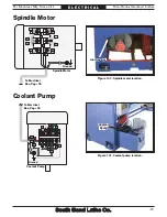
Page 99: ...ndle and pump motor Figure 140 Spindle motor location Ground U2 V5 W5 W2 V6 V1 U5 V2 U1 Gn U6 W1 W6 Spindle Motor U W V Junction Box Ground 3 2 1 4 6 5 W1 W1 V1 V1 U1 Gn Coolant Pump Coolant Pump Figu...

Page 100: ...eadstock Control Panel COMMON NC NC NO NO 3 4 1 2 NC NO 4 3 1 2 4 3 1 2 2 1 2 1 2 1 Ground 4 3 Emergency Stop Motor Start Pump Start Motor Stop Pump Stop Power Lamp 1 2 4 3 3 3 3 6 4 4 5 5 7 2 2 2 2 0...

Page 101: ...E E T L1 L2 L3 Inside Electrical Box Page 95 Headstock COMMON NC NC NO NO 3 4 1 2 NC NO 4 3 1 2 4 3 1 2 2 1 2 1 2 1 Ground 4 3 Emergency Stop Motor Start Pump Start Motor Stop Pump Stop Power Lamp 1...

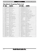
Page 102: ...d Lathes P A R T S Headstock Housing 1 1 1 1 2 2 3 3 4 4 5 5 6 6 7 7 8 8 9 9 10 10 11 11 12 12 13 13 14 14 15 16 17 18 19 20 21 22 23 24 25 26 27 28 29 29 29 29 29 30 31 32 32 32 32 33 33 34 34 35 36...

Page 103: ...For Machines Mfg Since 3 11 Turn Nado Gearhead Lathes 101 P A R T S Headstock Housing 2 53 54 55 56 57 58 59 60 61 62 63 64 65 65 66 67 68 69 69 70 71 71 72 73 74 75 76 77...

Page 104: ...MM 17 PSB1046PF0017 RANGE SELECTION LEVER 55 PK07M KEY 6 X 6 X 20 18 PK19M KEY 5 X 5 X 14 56 PRP76M ROLL PIN 4 X 16 19 PSB1046PF0019 SPEED SLECTOR SHAFT 57 PSB1046PF0057 FLANGE BUSHING 20 PK19M KEY 5...

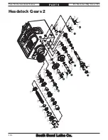
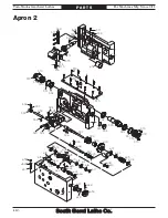
Page 105: ...9 120 121 122 123 124 125 126 127 128 129 130 127 131 132 133 134 135 136 137 138 139 140 141 142 143 144 145 146 147 148 149 149 150 151 152 153 124 154 155 156 157 157 158 159 160 161 122 162 163 16...

Page 106: ...186 187 187 187 187 188 188 188 188 189 190 191 122 192 193 143 143 141 162 162 139 143 194 194 194 194 194 194 195 196 196 196 197 198 199 200 201 202 203 204 205 206 179 207 208 208 209 210 211 212...

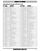
Page 107: ...PF0173 INBOARD COPPER COLLAR 124 PORG065 O RING 64 4 X 3 1 G65 174 P6906 OPEN BALL BEARING 6906 OPEN 125 PSB1046PF0125 PLUG 175 PSB1046PF0175 CLUTCH GEAR ASSY 27T 126 PORG055 O RING 54 4 X 3 1 G55 176...

Page 108: ...217 GEAR 27T 205 PSB1046PF0205 COMBO GEAR 24T 48T 218 PSB1046PF0218 SPACER 206 PSB1046PF0206 CHANGE GEAR SHAFT 219 PSB1046PF0219 GEAR 23T 207 PSB1046PF0207 COMBO GEAR 48T 24T 220 PSB1046PF0220 SPACER...

Page 109: ...11 312 313 314 314 315 316 317 318 318 319 320 321 322 323 324 325 326 327 328 329 330 331 331 332 333 334 335 336 337 338 339 340 341 342 343 344 345 346 347 348 349 350 351 352 329 330 329 308 353 3...

Page 110: ...4 385 385 385 386 387 388 389 390 391 392 393 394 392 393 394 395 396 397 398 399 400 401 401 402 403 404 404 404 405 405 405 406 406 406 407 408 409 410 411 412 412 412 413 413 413 414 415 415 415 41...

Page 111: ...PSB1046PF0324 SPACER 375 PSB1046PF0375 REVERSE STOP PLATE 325 PSB1046PF0325 GEAR 32T 376 PSB1046PF0376 UPPER LOWER PLATE 326 PSB1046PF0326 GEAR 23T 377 PSTB001 STEEL BALL 1 4 327 PSB1046PF0327 GEAR 1...

Page 112: ...B1046PF 48PF 423 PRP04M ROLL PIN 4 X 24 408 PSB1056F0408 GEARBOX COVER SB1056F 58F 424 PSB1046PF0424 SHIFT TAB 409 PSB1046PF0409 COUPLER 3 4 NPT 425 PSB1046PF0425 SHIFT FORK 410 PSB1046PF0410 ELBOW 3...

Page 113: ...509 510 511 512 513 514 514 514 514 514 514 515 516 517 518 519 520 521 522 523 523 524 525 526 526 527 528 528 528 529 530 531 532 532 533 534 534 535 536 537 538 539 540 541 542 543 545 546 548 547...

Page 114: ...58 558 558 568 569 572 573 574 575 576 577 578 579 579 580 580 581 581 582 583 582 582 584 548 585 586 587 588 589 590 591 592 593 594 595 596 597 598 599 600 601 602 603 604 605 606 607 608 609 610 6...

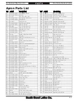
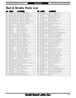
Page 115: ...L FLUTED RIVET 2 8 X 10 576 PSS28M SET SCREW M6 1 X 30 524 PSB1046PF0524 KNOB LABEL 577 PSB1046PF0577 PLUG 1 4 NPT 525 PSB1046PF0525 SHAFT 578 PSB1046PF0578 APRON TOP PLATE 526 PSB1046PF0526 GEAR SPAC...

Page 116: ...ROD OUTER SPACER 625 PSB1046PF0625 STEPPED SHAFT 610 PLN09M LOCK NUT M12 1 75 626 PORP018 O RING 17 8 X 2 4 P18 611 PSB1046PF0611 THRUST BEARING NTB1528 AS2 627 PSB1046PF0627 SHAFT END CAP 612 PSB1046...

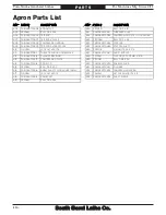
Page 117: ...0703 GEAR 24T SB1046PF 48PF 711 PSB1056F0711 GEAR 44T 56T SB1056F 58F 703 PSB1056F0703 GEAR 24T SB1056F 58F 712 PSB1046PF0712 SHAFT SLEEVE 704 PSB1046PF0704 PIVOT ARM SB1046PF 48PF 713 PSB1046PF0713 T...

Page 118: ...805 806 807 808 809 810 811 812 813 814 815 816 817 817 818 818 819 820 821 822 823 824 825 826 827 827 828 829 830 831 832 833 834 835 836 837 837 838 839 839 840 840 841 842 842 843 844 845 846 847...

Page 119: ...EW M10 1 5 X 25 816 PSB1046PF0816 IDLER ARM 845 PN02M HEX NUT M10 1 5 817 PR21M INT RETAINING RING 35MM 846 PSB1046PF0846 REAR MOTOR ACCESS PLATE 818 P6202ZZ BALL BEARING 6202ZZ 847 PBHS09M BUTTON HD...

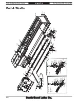
Page 120: ...905 931 906 907 908 908 909 910 911 912 913 914 915 916 917 918 919 920 920 921 921 922 923 924 924 925 925 926 927 928 929 930 931 930 931 932 932 933 934 935 936 937 938 939 940 941 942 942 943 944...

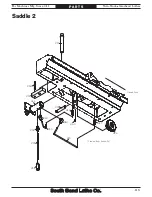
Page 121: ...For Machines Mfg Since 3 11 Turn Nado Gearhead Lathes 119 P A R T S Saddle 2 946 947 947 944 948 949 949 950 951 952 953 954 955 956 957 968 Viewed from beneath Headstock...

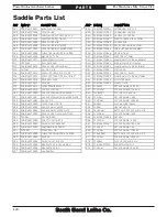
Page 122: ...0916 BEARING COVER 954 PSB1046PF0954 OIL FILTER 6MM 917 PSB1046PF0917 SPACER 955 PSB1046PF0955 CLAMP PLATE 918 PSB1046PF0918 LEADSCREW BRACKET 956 PSS44M SET SCREW M8 1 25 X 40 919 PSB1046PF0919 SADDL...

Page 123: ...1020 PSB1046PF1020 COMPOUND REST LEADSCREW W NUT 1006 PSB1046PF1006 POST SHAFT 1022 PK47M KEY 4 X 4 X 15 1007 PSB1046PF1007 TOOL POST PLUNGER 1023 PSB1046PF1023 THRUST BEARING NTB AS2 2035 1008 PSB10...

Page 124: ...6 1117 1118 1119 1120 1125 1126 1127 1128 1129 1130 1134 1135 1136 1137 1138 1139 1140 1145 1146 1147 1148 1149 1150 1155 1156 1157 1158 1159 1160 1161 1166 1167 1168 1169 1170 1171 1172 1172 SB1047PF...

Page 125: ...SB1047PF1159 SPINDLE ROD SB1047PF 58F 1110 PSB1046PF1110 GAP RACK SB1046PF 57F 1159 PSB1048PF1159 SPINDLE ROD SB1048PF 1110 PSB1047PF1110 GAP RACK SB1047PF 58F 1160 PSS20M SET SCREW M8 1 25 X 8 1110 P...

Page 126: ...1203 1204 1204 1205 1205 1205 1205 1205 1206 1206 1206 1206 1207 1208 1209 1210 1211 1212 1213 1214 1215 1216 1217 1218 1219 1220 1221 1222 1223 1223 1224 1224 1224 1225 1225 1225 1226 1227 1228 1229...

Page 127: ...ER SB1047PF 58F 1237 PSB1046PF1237 COOLANT PUMP ASSEMBLY 1209 PSB1046PF1209 CENTER PANEL BRACKET 1238 PSB1046PF1238 COOLANT TANK SB1046PF 48PF 1210 PBHS38M BUTTON HD CAP SCR M5 8 X 8 1238 PSB1056F1238...

Page 128: ...1206 1208 1209 1206 1207 1207 1207 1207 1207 1207 1208 1209 1210 1211 1212 1213 1214 1215 1216 1217 1218 1219 1220 1221 1222 1223 1224 1225 1226 1227 1228 1229 1230 1231 1232 1233 1234 1243 1244 1245...

Page 129: ...NT TANK COVER 1213 PSB1048PF1213 BRAKE LINKAGE COVER 1242 PS68M PHLP HD SCR M6 1 X 10 1214 PSB1048PF1214 BACKSPLASH MOUNTING PLATE 1243 PSB1048PF1243 RIGHT SIDE SPLASH TRAY 1215 PSB1046PF1214 CHUCK GU...

Page 130: ...25 X 25 1318 PLW03M LOCK WASHER 6MM 1360 PSB1046PF1360 CONTROL ARM BRACKET 1319 PSB1046PF1319 SHIELD PLATE 1364 PSB1046PF1364 STOP PLATE 1320 PSB1046PF1320 BRAKE DRUM 1365 PSB1046PF1365 STOP PLATE SH...

Page 131: ...PF1408 GRADUATED DIAL 1432 PSB1046PF1432 V WAY WIPER 1409 PSB1046PF1409 THRUST BEARING 3542AS2 1433 PSB1046PF1433 STRAIGHT WAY WIPER PLATE 1410 PSB1046PF1410 GRADUATED DIAL BASE 1434 PSB1046PF1434 STR...

Page 132: ...PF1507 GEAR SPACER 1508 PSB1046PF1508 DIAL GEAR 16T 1509 PCAP04M CAP SCREW M6 1 X 10 1511 PSS02M SET SCREW M6 1 X 6 1512 PN03M HEX NUT M8 1 25 REF PART DESCRIPTION 1600 PSB1046PF1600 MICROMETER STOP A...

Page 133: ...PF1706 CASTING 2PC SB1046PF 48PF 1706 PSB1056F1706 CASTING 2PC SB1056F 58F 1707 PSB1046PF1707 DOWEL PIN 1708 PSB1046PF1708 DOG PT LEAF SCREW M8 1 25 X 25 1709 PSB1046PF1709 HINGE PIN 1710 PSB1046PF171...

Page 134: ...B1046PF1911 TERMINAL BAR 17P 1902 PSB1046PF1902 OL RELAY AB 21 25A 1912 PSB1046PF1912 ELECTRICAL PANEL BACK PLATE 1903 PSB1046PF1903 MASTER POWER SWITCH 1913 PSB1046PF1913 STOP BUTTON 1904 PSB1046PF19...

Page 135: ...DRIVER 2 2003 SB1232 4 JAW CHUCK 14 2013 PWR1012 WRENCH 10 12MM 2004 PSB1042PF1804 DEAD CENTER MT 5 2014 PWR1417 WRENCH 14 17MM 2005 PSB1042PF1805 DEAD CENTER CARBIDE TIPPED MT 5 2015 PWR2224 WRENCH 2...

Page 136: ...es when using this machine or call 360 734 1540 to get a manual WARNING Only trained and properly supervised personnel are allowed to operate this machine If safe operation procedures are not clearly...

Page 137: ...erial Safety Data Sheets MSDS for WARNING ENTANGLEMENT HAZARD Remove or secure loose clothing hair or jewelry to reduce the risk of serious injury or death WARNING EYE INJURY HAZARD Always wear ANSI a...

Page 138: ......

Page 139: ...ne complies with the provisions of any law act code regulation or standard of any domestic or foreign government industry or authority In no event shall South Bend s liability under this warranty exce...

Page 140: ...South Bend Lathe Co P O Box 2027 Bellingham WA 98227 PHONE 360 734 1540 Administrative Offices FAX 360 676 1075 International FAX 360 734 1639 USA only southbendlathe com Printed In U S A BLTS14126...

Reviews: