background image

-108-

For Machines Mfg. Since 5/11

14" TURN-X

®

 Toolroom Lathe

P A R T S

Apron Rear View

450

451

452

453

454

455

456

458

459

461

462

463

465

466

467

468

469

470

472

473

474

475

476

477

478

479

480

481

482

483

491

494

495

496

497

414

434

422

497

473

434

Downloaded from 

www.Manualslib.com


manuals search engine


Summary of Contents for TURN-X SB1039

Page 1: ...ovember 2011 by South Bend Lathe Co For Machines Mfg Since 5 11 14 TURN X TOOLROOM LATHE MODEL SB1039 14 X 40 MODEL SB1052 14 X 30 OWNER S MANUAL Downloaded from www Manualslib com manuals search engi...

Page 2: ...through training and experience If you are not an experienced operator of this type of machinery read through this entire manual then learn more from an experienced operator schooling or research befo...

Page 3: ...on 25 Test Run 26 Spindle Break In 30 Recommended Adjustments 30 OPERATION 31 Operation Overview 31 Chuck Faceplate Mounting 32 Installation Removal Devices 32 Chuck Installation 33 Registration Marks...

Page 4: ...n Replacement 80 Gap Insert Removal Installation 82 Gap Removal 82 Gap Installation 83 TROUBLESHOOTING 84 ELECTRICAL 87 Electrical Safety Instructions 87 Correcting Phase Polarity Wiring 88 Wiring Ove...

Page 5: ...e purchased to help him change the world Capabilities This 16 Speed Toolroom Lathe is built for daily use in a busy industrial setting Loaded with many nice features and high precision parts this lath...

Page 6: ...d w Safety Switch E Steady Rest F Follow Rest G Halogen Work Lamp H 4 Way Tool Post I Compound Rest J Coolant Nozzle Valve K Tailstock see Page 7 for details Serious personal injury could occur if you...

Page 7: ...d chart to be active C Spindle Speed Lever Selects one of the four available spindle speeds within the selected speed range D Threading and Feed Charts Displays the necessary configuration of the gear...

Page 8: ...s oil from the apron reservoir to lubricate the carriage ways through various oil ports P Carriage Lock Secures the carriage in place when it should not move Q Thread Dial and Chart Dial indicates whe...

Page 9: ...lstock offset from the spindle centerline Figure 7 Tailstock controls AD AE Z AA AB AC AF Safety Foot Brake This lathe is equipped with a foot brake see Figure 9 to quickly stop the spindle instead of...

Page 10: ...84 lbs 2314 lbs Width side to side Depth front to back Height 90 x 45 x 69 79 x 45 x 69 Electrical Power Requirement 220V 3 Phase 60Hz Full Load Current Rating 14 4A Minimum Circuit Size 20A Switch Ma...

Page 11: ...Permanently Sealed Coolant Motor Type TEFC Induction Horsepower 1 8 HP Voltage 220V Phase 3 Phase Amps 0 4A Speed 3450 RPM Cycle 60 Hz Power Transfer Direct Drive Bearings Shielded Permanently Sealed...

Page 12: ...of Longitudinal Feeds 0 002 0 067 Number of Cross Feeds 17 Range of Cross Feeds 0 001 0 034 Number of Inch Threads 45 Range of Inch Threads 2 72 TPI Number of Metric Threads 39 Range of Metric Threads...

Page 13: ...Hardened Steel Bed Meehanite Castings with Precision Hardened and Ground Ways Stand Cast Iron Paint Urethane Other Country of Origin Taiwan Some Components Made in USA Japan Warranty 1 Year Serial Num...

Page 14: ...harm WILL occur Moderate injury or fire MAY occur Death or catastrophic harm COULD occur Machine or property damage may occur Basic Machine Safety Owner s Manual All machinery and machining equipment...

Page 15: ...g devices are properly secured and items attached to spindles have enough clearance to safely rotate Chuck Keys or Adjusting Tools Tools used to adjust spindles chucks or any moving rotating parts wil...

Page 16: ...A correct sharp tool decreases strain and provides a better finish Speed Rates Operating the lathe at the wrong speed can cause nearby parts to break or the workpiece to come loose which will result i...

Page 17: ...e risk of this hazard read and understand this document and seek additional training from an experienced chuck user before using a chuck Chuck Capacity Avoid exceeding the capacity of the chuck by cla...

Page 18: ...ags Mineral spirits Quality metal protectant oil Safety glasses Wrench or socket 21mm Wrench or socket 19mm Floor mounting hardware as needed Precision level Standard screwdriver 2 The purpose of the...

Page 19: ...If this machine will be connected to a shared circuit where multiple machines will be running at the same time consult a qualified electrician to ensure the circuit is properly sized A power supply ci...

Page 20: ...into a matching receptacle outlet that is properly installed and grounded in accordance with all local codes and ordinances see Figure 10 Figure 10 Typical NEMA 15 20 plug and receptacle Grounding Pi...

Page 21: ...m 1 K Phillips Screwdriver 2 1 L Standard Screwdriver 2 1 M Hex Wrench 8mm 1 N Tapered Spindle Sleeve MT 5 3 1 O Dead Center MT 3 1 P Carbide Tipped Dead Center MT 3 1 Q Camlock Key D1 5 1 R Tool Post...

Page 22: ...with a liberal amount of your cleaner or degreaser and let them soak for a few minutes 3 Wipe off the surfaces If your cleaner or degreaser is effective the rust preventative will wipe off easily Note...

Page 23: ...perated is important for safe operation and longevity of parts For best results operate this machine in a dry environment that is free from excessive moisture hazardous or flammable chemicals airborne...

Page 24: ...sure the carriage lock is loose the half nut is disengaged and the power feed is disengaged feed selection lever 5 Position hardwood blocks under each end of the bed as shown in Figure 14 This will k...

Page 25: ...how a distinct movement when a 0 003 shim approximately the thickness of one sheet of standard newspaper is placed under one end of the level See the figure below for an example of a high precision le...

Page 26: ...Oil Type Bolting to Concrete Floors The headstock quick change gearbox and apron oil reservoirs must have the proper amount of oil in them before the lathe can be operated for the first time Damage c...

Page 27: ...tic phase converter to create 3 phase power it can quickly decrease the life of electrical components on this machine If you must use a phase converter only use a rotary phase converter and connect th...

Page 28: ...n steps discussed in this manual have been followed and completed 4 Connect the incoming ground wire to the ground terminal directly above the master power switch 5 Make sure the power cord and wires...

Page 29: ...d Range Lever High Feed Range Lever Note In the next step use the chuck key to rock the chuck back and forth so that the gears will mesh as you make the adjustments Be sure to remove the chuck key bef...

Page 30: ...sition the spindle should be rotating counterclockwise down and toward you as you face the lathe If the spindle and chuck are not rotating counterclockwise the power supply is connected out of phase S...

Page 31: ...e spindle lever to the OFF position then replace the end gear cover 19 Lift the chuck guard up this will activate the chuck guard safety switch Reset the STOP button and attempt to start spindle rotat...

Page 32: ...tal particles are still suspended in the oil change the headstock and gearbox oil refer to Lubrication beginning on Page 66 for detailed instructions 6 Check the V belt tension and if necessary re ten...

Page 33: ...feed options to move the tooling into the workpiece for operations 12 When finished cutting moves the spindle lever to the OFF position presses the foot brake to completely stop the spindle then remov...

Page 34: ...determine the appropriate device to use refer to the following figure for examples Pre Threaded Hole for Lifting Eye Way Slot Jaw Slot Plywood 2x4 Chuck Cradle Plywood Chuck Cradle Straight Cuts Plyw...

Page 35: ...V s Figure 32 Correcting an improperly installed stud Stud Too High Turn In One Turn Stud Too Low Turn Out One Turn INCORRECT INCORRECT To install the chuck 1 DISCONNECT LATHE FROM POWER 2 Use an app...

Page 36: ...t was necessary to bump the chuck or use a mallet to release the tapers then they are seating together properly If the tapers released easily with little intervention they are not seated together firm...

Page 37: ...oor Unstable Workpiece Shallow Bar Stock Outside Safer Use Jaw Grip 4 Jaw Chuck Refer to the Chuck Installation see Page 33 and Chuck Removal see Page 34 instructions to install or remove the 4 jaw ch...

Page 38: ...llation see Page 33 and Chuck Removal see Page 34 instructions to install or remove the faceplate The faceplate included with your lathe can be used for a wide range of operations including machining...

Page 39: ...k lever backward away from the spindle to unlock the tailstock from the bedway 2 Slide the tailstock to the desired position 3 Push the tailstock lock lever forward toward the spindle to lock the tail...

Page 40: ...quill is retracted for tool removal Otherwise removal of such tooling may be difficult To install tooling in the tailstock 1 With the tailstock locked in place unlock the quill then use the handwheel...

Page 41: ...the back of the lathe to machine a taper at the spindle end Note The marks on the offset indicator are arbitrary For a precise offset use a dial indicator to check quill movement while adjusting the s...

Page 42: ...evel correct this condition before continuing with this procedure refer to Leveling Mounting on Page 23 2 Center drill both ends of one piece of round stock then set it aside for use in Step 5 3 Use t...

Page 43: ...r Looking down from above Figure 48 Adjust tailstock away from the operator Centers Figure 49 shows the MT 5 dead centers included with the lathe In addition an MT 7 MT 5 tapered spindle sleeve is inc...

Page 44: ...ng a lathe dog and faceplate for turning between centers Mounting Center in Tailstock Either a carbide tipped dead center or live center can be used in the tailstock Mounting instructions are the same...

Page 45: ...f the center does not come loose by retracting the quill extend the quill to expose the slot shown in Figure 52 then use a drift key to remove the center Figure 52 Drift key slot in the side of the qu...

Page 46: ...crews so the finger roller positions can be adjusted 6 Use the finger adjustment knobs to position the bottom two finger rollers against the workpiece as shown in the example of Figure 55 7 Close the...

Page 47: ...cts of friction lubricate the brass finger tips with generous lubricant during operation Figure 56 Follow rest attachment Cap Screws Carriage Slide Locks The carriage cross slide and compound rest hav...

Page 48: ...e compound rest for cutting threads mark the location on the cross slide as a quick reference point This will allow you to quickly return the compound rest to that exact angle the next time you need t...

Page 49: ...n Page 40 for detailed instructions Make a facing cut on a piece of round bar stock If the tool is above or below the spindle centerline a nub will be left in the center of the workpiece Adjust the he...

Page 50: ...m the feed rod and movement stops Figure 63 Adjustable feed rod stop Stop Collar Stop Plate Apron The adjustable feed stop system is designed to stop longitudinal carriage movement at the desired loca...

Page 51: ...safe and satisfactory results as well as maximizing tool life To set the spindle speed for your operation you will need to 1 Determine the best spindle speed for the cutting task and 2 configure the...

Page 52: ...s to make changes Figure 67 Spindle speed controls Motor Switch Spindle Speed Range Levers Configuration Examples Using the controls on the lathe follow along with these two examples for setting the s...

Page 53: ...ntrolled by the headstock and quick change gearbox lever positions and the end gear configuration Feed rate and spindle speed must be considered together Keep in mind that the feed rate is expressed i...

Page 54: ...the middle position disables power feed B Feed Direction Lever When the lathe is stopped selects the direction for power feed Note When the lathe is running use the quick change feed direction knob on...

Page 55: ...waiting until the spindle is stopped then using the feed direction lever on the headstock When using power feed to move the cross slide the feed rate is 1 2 the value stated in the feed rate chart Se...

Page 56: ...CT1W 002 055 LCT2W 0022 065 LCT4W 003 085 LCT8W 0033 10 LCS2W 004 13 LCS4W 005 18 LCS8W 007 22 LCR3W 009 28 LCR4W 011 35 LCR8W 014 44 LCS8X 017 55 LCR2X 022 68 LCR3X 027 85 LCR8X 033 1 2 HCS2X 047 1 4...

Page 57: ...keep the arm in place 5 Use a stiff brush and mineral spirits to clean away the debris and grime from the gears and shafts then lubricate these devices as instructed in the End Gears lubrication subse...

Page 58: ...ated in Figure 77 Threading Figure 77 Metric thread chart with 1 75 TPmm highlighted 2 LT1Z 225 LT2Z 25 LT3Z 3 LT6Z 35 LT8Z 4 LS1Z 45 LS2Z 5 LS3Z 6 LS6Z 7 LS8Z 75 LT6Y 8 LR1Z 1 2 LR6Z 1 25 LS3Y 1 3 LR...

Page 59: ...rol Lever Half Nut Lever Thread Dial The numbers on the thread dial are used with the thread dial chart to show when to engage the half nut during inch threading The thread dial gear must be engaged w...

Page 60: ...half nut engaged from the beginning until the turning is complete for these types of operations The following examples explain how to use the thread dial chart TPI Divisible By 4 For threading a TPI...

Page 61: ...Half nut stays engaged for 27 8 TPI 27 8 Same as Metric Threads Thread Dial Not Used The chip drawer catches swarf and metal chips during the machining process It contains a screen that keeps the lar...

Page 62: ...nts Sulferized Oil Mineral OIl Figure 89 Coolant selection table Coolant System When the coolant pump is turned ON the fluid is delivered through the nozzle attached to the carriage The flow is contro...

Page 63: ...the gear cover The Model SB1264 is capable of delivering years of trouble free service It is manufactured with the same high quality workmanship materials and tolerances South Bend machinery is known...

Page 64: ...close to zero TIR Total Indicated Runout as can be Keyless chuck self tighten so a spanner is provided to ease tool removal Figure 94 MT 3 Keyless Chuck SB1354 South Bend Cast Iron Workbench Legs 1 P...

Page 65: ...turing boring holder boring bar holder parting blade holder knurl facing holder and tool post w T nut Figure 98 SB1408 Quick Change Tool Post Set SB1251 Machinist s Oak Tool Box Proudly made in the S...

Page 66: ...rved at all times to minimize the risk of injury or machine damage If any of the conditions below are observed stop the lathe immediately disconnect power and correct the condition before resuming ope...

Page 67: ...rvice Item Change Gearbox Oil Change Headstock Oil Change Apron Oil Change Coolant Annual Service Make copies of this page to use each month Keep each chart as a maintenance record for your South Bend...

Page 68: ...his manual could lead to premature failure of lathe components and will void the warranty Figure 100 Location of headstock oil sight glass Headstock Oil Sight Glass Adding Oil The oil fill plug is loc...

Page 69: ...ug Drain Plug Draining Oil Place a catch pan under the quick change gearbox drain plug see Figure 103 use a 5 8 wrench to loosen the fill plug and remove the drain plug then allow the gearbox reservoi...

Page 70: ...l range of movement to distribute oil along the ways Lubricate the guides before and after operating the lathe If the lathe is in a moist or dirty environment increase the lubrication interval Check t...

Page 71: ...move any dust or grime Push the rubber or plastic tip of the oil can nozzle against the ball oiler to create a hydraulic seal then pump the oil can once or twice If you see sludge and contaminants com...

Page 72: ...ebris from the outside environment Lubricating 1 DISCONNECT LATHE FROM POWER 2 Remove the end gear cover and all the end gears shown in Figure 110 3 Clean the end gears thoroughly with mineral spirits...

Page 73: ...hen the tank is regularly cleaned however if too much sludge is allowed to accumulate before the tank is cleaned the pump will inevitably begin sucking it up Hazards As coolants ages and gets used dan...

Page 74: ...ch tray and fluid tank The entire job only takes about a 1 2 hour when you are prepared with the proper materials and tools Make sure to dispose of old fluid according to federal state and fluid manuf...

Page 75: ...ROM POWER 4 Thoroughly clean all unpainted bare metal surfaces then apply a liberal coat of way oil heavy grease or rust preventative Take care to ensure these surfaces are completely covered but that...

Page 76: ...pound rest backlash adjustment set screws Set Screws Reducing backlash to less than 0 002 is impractical and can lead to accelerated wear of the wedge nut and leadscrew Avoid the temptation to overtig...

Page 77: ...he gib screws as necessary to make it tighter or looser The gib adjustment process usually requires some trial and error Repeat the adjustment process as necessary until you find the best balance betw...

Page 78: ...he clamping pressure between the upper and lower castings Test the gib adjustment by using the offset adjustment screws When you are satisfied with the setting retighten the clamping hex bolts Figure...

Page 79: ...es not become tighter than the other 3 Engage disengage the half nut several times and notice how it feels The half nut is correctly adjusted when it has a slight drag while opening and closing The mo...

Page 80: ...ant that the brake is kept properly adjusted so you can quickly stop the spindle in an emergency Tools Needed Qty Phillips Screwdriver 2 1 Hex Wrench 6mm 1 To adjust the brake and brake switch 1 DISCO...

Page 81: ...al Stop Pedal Lever Brake Belt Band 10 Push the pedal lever down to verify that the cam lobe pushes the brake switch plunger in When pushed in the switch should click If the switch does not click loos...

Page 82: ...If you fabricate your own shear pin make sure to use the material and dimensions specified in Figure 129 Otherwise the shear pin may not provide the intended protection and lathe damage could result 9...

Page 83: ...n does not freely slide into the bore DO NOT use a hammer on the pin or you may permanently damage the shear mechanism and bore which would make it nearly impossible to remove and install a new shear...

Page 84: ...nment Therefore if the gap insert is removed it may be difficult to re install with the same degree of accuracy Gap Insert Removal Installation Figure 136 Gap insert Gap Insert 2 Remove the two way en...

Page 85: ...igned If necessary loosen the gap bed cap screws and repeat Steps 7 8 until the insert is properly aligned Gap Installation 1 Use mineral spirits and a clean lint free rag to clean the mating surfaces...

Page 86: ...rify electrical box door chuck guard spindle and brake switches are not engaged 8 Thermal overload relay has tripped 8 Turn the thermal relay cut out dial to increase working amps and push the reset p...

Page 87: ...all the way back into the tailstock 1 Turn the quill handwheel until it forces the tapered tool out of quill 2 Contaminants not removed from taper before inserting into quill 2 Clean the taper and bor...

Page 88: ...ing turning operations 5 Bedways are dry and in need of lubrication 5 Lubricate bedways and handles 6 Micrometer stop is interfering 6 Check micrometer stop position and adjust it as necessary see Pag...

Page 89: ...or fire Motor Wiring The motor wiring shown in these diagrams is current at the time of printing but it may not match your machine Always use the wiring diagram inside the motor junction box Circuit R...

Page 90: ...sh the STOP button turn the master power switch to OFF and disconnect the machine from power 2 Open the electrical box and swap any two hot wires coming from the plug as illustrated in Figure 138 To P...

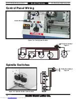
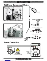
Page 91: ...mp Page 95 Coolant Pump Motor Page 92 Spindle Switches Behind Splash Guard Page 94 Spindle Motor Page 92 Control Panel Page 94 Chuck Guard Safety Switch Page 95 End Gear Cover Safety Switch Page 95 Br...

Page 92: ...00MA 250V 0 220 0 220 380 400 415 440 TRANSFORMER Suenn Liang SP TBSW 10140 7 6 5 4 3 2 1 0 A1 W1 V1 U1 R1 S1 8 T1 L3 L2 Ground 3 3 3 3 2 2 2 2 1 1 1 0 0 0 3 3 4 4 4 4 4 5 5 5 6 6 6 6 6 7 7 7 8 3 3 3...

Page 93: ...For Machines Mfg Since 5 11 14 TURN X Toolroom Lathe 91 E L E C T R I C A L Figure 140 Electrical box Electrical Box Downloaded from www Manualslib com manuals search engine...

Page 94: ...W1 LOW LOW Coolant Pump Motor Spindle Motor CUTTING FLUID PUMP MOTOR 440V U1 V1 W6 W2 U2 LOW Ground Ground 3 2 1 4 6 5 W1 W1 V1 V1 U1 Gn 3 2 1 4 6 5 W1 W1 V1 V1 U1 Gn U5 W5 Ground HI U1 V1 Coolant Pum...

Page 95: ...h Sides Shown Front View Rear View 6 S 4 1 3 T 2 R 5 R1 R1 T1 T1 S1 S1 LOW LOW LOW LOW LOW LOW HI HI HI HI HI HI 2 Speed Motor Switch Figure 143 2 Speed motor switch 2 Speed Motor Switch To Electrical...

Page 96: ...MON NC NO NO X1 X2 4 4 3 3 2 1 13 14 21 22 NC NC NO NO 3 4 4 5 5 7 7 6 6 X 2 A1 X 1 Ground 4 2 2 2 2 6 2 2 2 8 3 1 2 6 8 3 1 Spindle Switches Figure 145 Spindle rotation switch location COMMON NC COMM...

Page 97: ...t Page 90 Inside Electrical Cabinet Page 90 Figure 146 End Gear Cover Safety switch location End Gear Cover Safety Switch Headstock COMMON NC NO COMMON X A1 0 0 2 Coolant Pump Switch Jog Button Power...

Page 98: ...T S Headstock Cover 1 2 3 4 REF PART DESCRIPTION REF PART DESCRIPTION 1 PSB10390001 HEADSTOCK OIL FILL CAP 3 PSB10390003 HEADSTOCK COVER 2 PCAP29M CAP SCREW M6 1 X 40 4 PSB10390004 HEADSTOCK COVER GA...

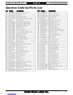
Page 99: ...Controls 5 6 7 8 9 10 11 12 13 14 15 16 17 18 19 20 21 22 23 24 25 26 27 28 29 30 31 32 33 34 35 36 37 38 39 44 41 42 43 40 45 46 47 48 49 50 51 52 53 54 55 56 57 58 59 60 61 62 63 64 6 30 28 52 49 9...

Page 100: ...16 O RING 15 8 X 2 4 P16 18 PSB10390018 SHIFT CAM WHEEL 48 PSB10390048 SHAFT END CAP 19 PSB10390019 SHIFT SHAFT BUSHING 49 PCAP10M CAP SCREW M5 8 X 15 20 PCAP17M CAP SCREW M4 7 X 10 50 PSB10120044 SHI...

Page 101: ...stock Internal Gears 65 66 67 69 70 71 72 73 74 75 76 77 78 79 82 83 84 85 86 87 88 89 90 91 92 93 94 95 96 97 98 99 100 101 102 103 104 105 106 107 108 109 110 111 112 113 114 115 116 117 38 69 68 68...

Page 102: ...5 PORP028 O RING 27 7 X 3 5 P28 103 PSB10390103 KEY 10 X 6 X 85 76 PSB10390076 PULLEY SHAFT SPACER 104 PK109M KEY 7 X 7 X 35 77 PSB10120079 SPINDLE PULLEY FLAT WASHER 105 PCAP07M CAP SCREW M6 1 X 30 7...

Page 103: ...6 COMBO GEAR 21T 21T 83 PR11M EXT RETAINING RING 25MM 137 PSB10120119 LOWER GEAR SHAFT 85 PR09M EXT RETAINING RING 20MM 139 PSB10390139 GEAR 21T 121 PSB10390121 SPINDLE BALANCE SLEEVE 140 PSB10120121...

Page 104: ...0 211 212 213 214 215 216 217 218 219 220 221 222 223 224 225 226 227 228 229 230 231 232 233 234 235 236 237 238 239 240 241 242 243 244 245 246 247 248 249 250 251 252 253 254 255 256 257 258 259 26...

Page 105: ...22T 215 PR11M EXT RETAINING RING 25MM 246 PSB10120246 GEAR 22T 216 PSB10120216 SPLINED SHAFT G2 247 PSB10120247 GEAR 33T 217 PSB10120217 SPLINED SHAFT G3 248 PSB10120248 GEAR 22T 218 PSB10390218 WOOD...

Page 106: ...4 275 276 277 278 279 280 281 282 283 284 285 286 287 288 289 290 291 292 293 294 295 296 297 298 299 300 301 302 303 305 306 307 308 309 310 311 312 313 314 315 316 317 318 319 320 321 322 323 325 32...

Page 107: ...SB10120279 LEFT UPPER SHIFT FORK 319 PSB10120319 SHIFT LEVER 280 PSB10120278 RIGHT UPPER SHIFT FORK 320 PSB10120314 SHIFT LEVER WASHER 281 PRP02M ROLL PIN 3 X 16 321 PSB10120321 SHIFT LEVER END CAP 28...

Page 108: ...404 405 406 407 408 409 410 411 412 413 414 415 416 417 418 419 420 421 422 423 424 425 426 427 428 429 430 431 432 434 435 437 438 439 440 441 442 444 445 446 447 448 449 484 485 486 487 488 489 490...

Page 109: ...EED SELECTOR LEVER 442 PSB10120542 CARRIAGE GRADUATED DIAL 413 PSB10120513 FEED SELECTOR PINION SHAFT 444 PSB10120515 COMPRESSION SPRING 414 PSTB001 STEEL BALL 1 4 445 PSB10120545 CARRIAGE HANDWHEEL 4...

Page 110: ...Lathe P A R T S Apron Rear View 450 451 452 453 454 455 456 458 459 461 462 463 465 466 467 468 469 470 472 473 474 475 476 477 478 479 480 481 482 483 491 494 495 496 497 414 434 422 497 473 434 Down...

Page 111: ...0390454 CYLINDRICAL ROLLER BEARING 2930 477 PSB10120577 HALF NUT PIVOT ARM 455 PSB10120555 THRUST WASHER 478 PSB10120578 PIVOT ARM BRACKET 456 PR11M EXT RETAINING RING 25MM 479 PSB10120579 HALF NUT 45...

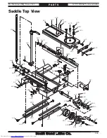
Page 112: ...RESSION SPRING 6 X 27MM 525 PSS03M SET SCREW M6 1 X 8 509 PSB10120909 TOOL POST T SLIDER 526 PCAP02M CAP SCREW M6 1 X 20 510 PSB10120910 COMPOUND SLIDE 527 PRIV001M STEEL FLUTED RIVET 2 X 5MM 511 PSB1...

Page 113: ...605 606 607 608 609 610 613A 614 615 616 617 618 619 620 621 622 623 624 625 626 627 628 629 630 631 632 633 634 635 636 637 638 639 640 654 655 656 657 658 659 660 661 662 663 664 666 667 668 601 60...

Page 114: ...T 614 PK168M KEY 3 X 3 X 80 651 PSB10121051 ONE SHOT OILER ASSEMBLY 615 PRP28M ROLL PIN 5 X 40 654 PK52M KEY 3 X 3 X 15 616 PSB10390616 CUTTING FLUID NOZZLE 3 8 PT X 24 655 PLUBE001 TAP IN BALL OILER...

Page 115: ...GHT PIPE ADAPTER 1 8 PT X 4MM 652 PSB10121052 SADDLE STOP BLOCK 645 PSB10390645 ALUMINUM OIL PIPE 4 X 260MM 665 PSS03M SET SCREW M6 1 X 8 646 PSB10390646 ELBOW PIPE ADAPTER 1 8 PT X 4MM 669 PCAP24M CA...

Page 116: ...0 1 5 X 20 709 PSB10120809 COPPER PLUNGER 710 PSS06M SET SCREW M8 1 25 X 16 711 PSB10390711 DOG POINT SET SCREW M8 1 25 X 12 712 PSS14M SET SCREW M8 1 25 X 12 Dial Indicator 751 752 753 754 755 757 75...

Page 117: ...812 813 814 815 816 817 818 819 820 821 822 823 824 825 826 827 828 829 830 831 832 833 834 835 836A 838 839 840 841 842 843 844 845 846 847 848 849 850 851 852 853 854 855 856 857 858 859 860 861 862...

Page 118: ...VOT ARM 818 PSB10390818 SPINDLE ON OFF LEVER KNOB 854 PEC09M E CLIP 6MM 819 PSB10121212 SPINDLE ON OFF LEVER 855 PSB10390855 SPINDLE SWITCH LINKAGE ROD 820 PN09M HEX NUT M12 1 75 856 PSB10390856 SPIND...

Page 119: ...X 7 X 30 905 PK166M KEY 7 X 7 X 15 915 PSB10121840 PIVOT ARM ALL THREAD STUD 906 PN32M HEX NUT M14 2 916 PCAP14M CAP SCREW M8 1 25 X 20 907 PSB10121407 GEAR FLAT WASHER 917 PSB10390917 GEAR FLAT WASH...

Page 120: ...1011 1012 1013 1014 1015 1016 1017 1018 1019 1020 1021 1022 1023 1024 1025 1026 1027 1028 1029 1030 1031 1032 1033 1034 1035 1036 1037 1038 1039 1040 1041 1042 1043 1044 1045 1046 1047 1048 1049 1049...

Page 121: ...PHLP HD SCR M4 7 X 30 1013 PSB10391013 MOTOR MOUNT PLATE 1039 PSB10121209 CAST IRON FOOT PAD 1014 PCAP64M CAP SCREW M10 1 5 X 25 1040 PB51M HEX BOLT M16 2 X 50 1015 PCAP01M CAP SCREW M6 1 X 16 1041 P...

Page 122: ...5 1106 1107 1108 1109 1110 1111 1112 1115 1116 1117 1118 1119 1120 1121 1122 1123 1124 1125 1126 1127 1128 1129 1130 1131 1132 1133 1134 1135 1136 1137 1138 1139 1140 1141 1142 1143 1144 1106 1107 110...

Page 123: ...HEX NUT M12 1 75 1109 PCAP02M CAP SCREW M6 1 X 20 1134 PCAP129M CAP SCREW M12 1 75 X 20 1110 PSB10391110 FLANGE BEARING 1135 PSB10121629 CHUCK GUARD PIVOT ROD 1111 PSB10391111 CENTER PANEL BRACKET 113...

Page 124: ...1208 1209 1210 1211 1212 1213 1214 1215 1216 1217 1218 1219 1221 1222 1223 1224 1225 1226 1227 1228 1229 1230 1231 1232 1233 1234 1235 1236 1237 1238 1239 1240 1241 1242 1243 1244 1245 1246 1247 1248...

Page 125: ...4 2 X 110 1212 PSB10121812 HANDWHEEL HANDLE 1240 PCAP01M CAP SCREW M6 1 X 16 1213 PSB10120515 COMPRESSION SPRING 6 2 X 16MM 1241 PSS04M SET SCREW M6 1 X 12 1214 PSTB001 STEEL BALL 1 4 1242 PCAP26M CAP...

Page 126: ...INGE PIN 1315 PSB10122015 DOG PT LEAF SCREW M8 1 25 X 25 1316 PN09M HEX NUT M12 1 75 1317 PW06M FLAT WASHER 12MM 1318 PSB10391318 STUD DE M14 2 X 80 28 35 1319 PSB10122019 CLAMP PLATE Steady Rest Foll...

Page 127: ...391411 JOG BUTTON 1403 PSB10391403 MASTER POWER SWITCH 1412 PSB10122222 EMERGENCY STOP BUTTON 1404 PSB10391404 OL RELAY AB 193 TAC24 A 17 5 21 5A 1413 PSB10391413 POWER LAMP 1405 PSB10391405 OL RELAY...

Page 128: ...2 FACEPLATE CAMLOCK STUD SET 1515 PSDP2 SCREWDRIVER PHILLIPS 2 1504 PSB10391504 3 JAW CHUCK KEY 1516 PAW1510M HEX WRENCH SET 10PC 1 5 10MM 1505 PSB10391505 4 JAW CHUCK KEY 1517 PSB10122317 TOOLBOX 15...

Page 129: ...is machine MUST maintain the original location and readability of these safety labels If any label is removed or becomes unreadable REPLACE that label before using the machine again Contact South Bend...

Page 130: ...ABEL 1618 PSB10391618 SB1039 MODEL NUMBER LABEL 1606 PSBLABEL08HS ENTANGLEMENT HAZARD LABEL 1618 PSB10521618 SB1052 MODEL NUMBER LABEL 1607 PSB10122411 CHUCK KEY HAZARD LABEL 1619 PSBPAINT02 SB LIGHT...

Page 131: ...ons of any law act code regulation or standard of any domestic or foreign government industry or authority In no event shall South Bend s liability under this warranty exceed the original purchase pri...

Page 132: ...Printed In U S A TS14364 Downloaded from www Manualslib com manuals search engine...

Reviews: