background image

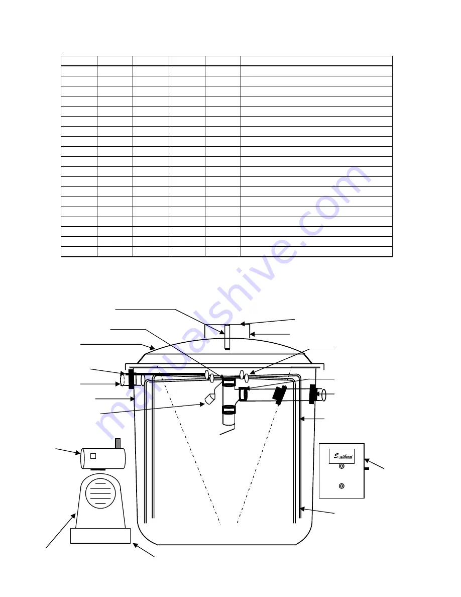
15.Comp. Cover

17. Control Panel

PART NO. PART NO. PART NO. PART NO. PART NO. DIAGRAM NUMBER            DESCRIPTION

SM-501

SM-601

SM-701

SM-1001

SM-1501    1.        FIBERGLASS AERATION TANK

SM-502

SM-602

SM-702

SM-1002

SM-1502    2.        P.E. or F.G. CLARIFIER CONE

SM-503

SM-603

SM-703

SM-1003

SM-1503    3.        FIBERGLASS DOME LID 

SM-504

SM-604

SM-704

SM-1004

SM-1504    4.        P. E. RISER 24"X6" 

SM-505

SM-605

SM-705

SM-1005

SM-1505    5.        P. E. RISER LID 24"

SM-506

SM-606

SM-706

SM-1006

SM-1506    6.        PVC Union  (TYP. 4)

SM-507

SM-607

SM-707

SM-1007

SM-1507    7.        PVC AIR INLET LINE

SM-508

SM-608

SM-708

SM-1008

SM-1508    8.        PVC FOUR WAY CROSS

SM-509

SM-609

SM-709

SM-1009

SM-1509    9.        PVC AIR DROP LINE (TYP. 4)

SM-510

SM-610

SM-710

SM-1010

SM-1510   10.       PVC AIR DIFFUSER (TYP. 4) Optional 

SM-511

SM-611

SM-711

SM-1011

SM-1511   11.       4" SCH 40 PVC INLET

SM-512

SM-612

SM-712

SM-1012

SM-1512   12.       4" SCH 40 PVC OUTLET ASSEMBLY

SM-513

SM-613

SM-713

SM-1013

SM-1513   13.       NEOPRENE SEAL (TYP. 3)

SM-514

SM-614

SM-714

SM-1014

SM-1514   14.       AIR COMPRESSOR

SM-515

SM-615

SM-715

SM-1015

SM-1515   15.       COMPRESSOR COVER

SM-516

SM-616

SM-716

SM-1016

SM-1516   16.       COMPRESSOR BASE

SM-517

SM-617

SM-717

SM-1017

SM-1517   17.       CONTROL PANEL

SM-518

SM-618

SM-718

SM-1018

SM-1518   18.       SENSOR FLOAT

SM-519

SM-619

SM-719

SM-1019

SM-1519   19.       SAMPLE STACK

16. Comp. Base

2. Clarifier Cone

14. Air Compressor

SM500    SM600    SM750    SM1000   SM1500

MODEL NO.’S

PARTS LIST & DIAGRAM

1. Aeration Tank

3. Lid Dome

7. Air Inlet Line

9. PVC Air Drop Line (TYP. 4)

10. Air Diffuser (TYP. 4)

OPTIONAL

11. PVC Inlet

12. PVC Outlet  Pipe & Tee’s

13. Neoprene Seal (TYP. 3)

4. PE Riser 24”Dia. x 6”H

5. PE  Riser Lid 24” Dia.

6. PVC Union  (TYP. 4)

8. Four way Cross

19. Sample Stack

Note:  Sensor float is located in pump tank on all spray irrigation disposal systems 

HIGH WATER 

ALARM

AIR COMPRESSOR

FAILURE

18. High Water Alarm 

Sensor Float

Rev. By RC 07/30/01

9

Summary of Contents for SM1000 - F

Page 1: ...600 F MODEL SM750 F MODEL SM1000 F MODEL SM1500 F 500 G P D 500 G P D 500 G P D 600 G P D 750 G P D 1000 G P D 1500 G P D OWNER S MANUAL SOUTHERN MFG CO PO BOX 790 GROVES TX 77619 PHONE 409 962 4501 F...

Page 2: ...wastewater is becoming ever more important That is why it s very important you read this owners manual in it s entirety and follow all instructions Today an aerobic treatment plant is in the back yar...

Page 3: ...organic matter by settling of the solids in the inner cone shaped clarifier where conditions are calm Each time wastewater enters the plant the mixed liquor is forced upward through the hole at the bo...

Page 4: ...t the control panel the light will remain on until the water returns to a normal level 5 Your on site sewage facility has a particular type of disposal field depending on your local and state code As...

Page 5: ...ompany pumper Maintenance Company Qualifications A State septic system installer license or wastewater treatment plant operator license must be held by at least one person in the maintenance company a...

Page 6: ...the diffusers speeds up the return of aerobic bacteria that treats the wastewater from the home 5 Have all tanks completely pumped out and immediately start refilling through trash tank until the trea...

Page 7: ...g toilets faucets or excessive water usage may cause discharge of untreated wastewater 7 Air conditioning or refrigerator freezer condensate drains should not be allowed into the plant as the addition...

Page 8: ...ion the system should be examined for proper operation by an authorized service provider The predicted service associated with the system includes Treatment Plant 1 Clean intake felts on top of air co...

Page 9: ...FLOW DIAGRAM INFLUENT EFFLUENT 8...

Page 10: ...SM 1012 SM 1512 12 4 SCH 40 PVC OUTLET ASSEMBLY SM 513 SM 613 SM 713 SM 1013 SM 1513 13 NEOPRENE SEAL TYP 3 SM 514 SM 614 SM 714 SM 1014 SM 1514 14 AIR COMPRESSOR SM 515 SM 615 SM 715 SM 1015 SM 1515...

Page 11: ...ng 1 11 GPM Max Loading 1 67 GPM BOD Loading 1 25 LBS Model SM600 600 GPD Design Loading 1 33 GPM Max Loading 2 00 GPM BOD Loading 1 5 LBS Model SM750 750 GPD Design Loading 1 67 GPM Max Loading 2 50...

Page 12: ...HEIGHT G 7 2 7 2 Model s SM500 5X5 F SM500 5X8 F QUICK EASY DIMENSIONAL DRAWING The Inner Crescent Represents the 540 Gal Pump Tank The Outer Crescent Represents the 800 Gal Pump Tank Effluent Dischar...

Page 13: ...9 10 RISER I D C 1 8 1 8 1 8 1 8 1 8 TANK I D D 6 2 6 6 6 8 7 2 7 3 TANK O D E 6 7 6 11 6 11 7 7 7 8 TANK HEIGHT I D F 5 5 5 11 7 1 7 6 10 8 GRADE LEVEL G 5 10 6 4 7 6 7 11 11 3 DIMENSIONAL DRAWING O...

Page 14: ...components or material or loss incurred because of interruption of service or for any other special or consequential damages or incidental expenses arising from the manufacture sale or use of this sy...

Page 15: ...ird copy shall be sent to the owner List the appropriate test method s and frequency Chlorine Residual BOD Grab TSS Grab or Fecal Coliform that is required by local or state regulations for this speci...

Page 16: ...FOR SERVICE CALL AUTHORIZED SERVICE PROVIDER Company Name Phone Address...

Reviews: