background image


LGCY Series 

Page  2 


Chapter I Equipment Overview and Safety Warning 

1  Equipment Overview 

The LGCY series of air compressor is elaborately designed and manufactured by us for customers, mainly 
powered by diesel engine, connected with the air compressor handpiece through coupling to generate air and 
further drive pneumatic tools such as jack drill to operate and drill holes; its feature is to operate under the 
outdoor environment without electricity. 

Note: Only a trained and authorized person can operate the compressor. The operator shall carefully 
read this manual and fully understand its contents before operation. Accidents, casualties and or death 
may occur in the case of failure to follow the operation procedure and safety precautions herein.


Warning: Do not start the unit under unsafe condition; if a fault has occurred, do not try to start the 
equipment. Instead, switch off the equipment  and  make evident identification  to prevent incorrect 
operation by others, the use of the “Lock Out Tag Out” safety process is recommended. 
Hazard:  Compressed air is hazardous. Competent suitably trained persons  can only repair and 
maintain the unit after ensuring the pressure in the compressor system has been released. 

The installation use and maintenance of equipment must be in accordance with relevant laws, regulations and 
standards. 
Unless approved by us, do not modify the internal structure and control method of unit. 
Carry out routine maintenance, carefully inspect the units every day, and check for leaks, lose components, 
damage or improper adjustments. If there is any abnormality, the compressor may not be used until the faults 
are rectified. 

Personnel Protection: 

Before installing and operating the equipment, all personnel shall be familiar with and follow the operation 
procedure and specifications on personal protection equipment in local regulations, including but not limited 
to  eye, face, hearing and respiratory protection, limb protection equipment, protective clothing, protection 
plate, electric shock protection equipment and noise protection equipment. 

2  Safety Warning 

2.1 Lifting 

2.1.1 The equipment for lifting compressor shall be suitable and conform to local safety specifications. 

2.1.2  Inspect the lifting frame, lifting ring crack  and bolt and nut looseness  before lifting the 
compressor. 
2.1.3 Remove or fix all loose parts that may fall off and fix the rotational parts such as door and pull 
rod. 
2.1.4 Tether the equipment with rope during lifting to prevent the equipment rotating after lifting. 
2.1.5 Do not lift the equipment when environmental conditions increase the hazard such as strong or 
unstable winds. 

Summary of Contents for JCD-900 Series

Page 1: ...DIESEL ENGINE PORTABLE ROTARY SCREW AIR COMPRESSOR INSTRUCTION MANUAL Model LGCY27 10 LGCY32 10SERIES...

Page 2: ...y make improvement to the product The user shall note that the contents herein may be different from the actual conditions of product after a period If this manual does not clearly describe any aspect...

Page 3: ...g 2 Chapter II Structure and Operating Principle 9 Chapter III Main Performance and Technical Parameters 24 Chapter IV Installation and Commissioning Adjustment 25 Chapter V Use and Operation 26 Chapt...

Page 4: ...e installation use and maintenance of equipment must be in accordance with relevant laws regulations and standards Unless approved by us do not modify the internal structure and control method of unit...

Page 5: ...n 15 B Follow the local specifications on road traffic safety C Do not exceed the free steering angle for forward or reverse travel Do not drag the equipment barbarously D Avoid obstacles such as pit...

Page 6: ...boiling before fully unscrewing the radiator cap 2 4 Fire Hazard and Explosion A When refuelling the compressor use a refuelling station Otherwise connect the compressor and refuelling equipment to th...

Page 7: ...re doors and panels must be securely fastened to ensure the safety of operators B Do not operate the compressor after the protective cover of fan or other components is removed C Wear appropriate pers...

Page 8: ...en Do not direct either discharge ports at operators or other persons H If diethyl ether or anti freeze agent is splashed into your eyes rinse immediately with plenty of water and immediately seek med...

Page 9: ...p and other metal parts to prevent a fire due to electric arc I Generally the positive pole of the battery is marked with the words and POS and the negative pole is marked with the words and NEG J Sta...

Page 10: ...ease note that the cleaning liquid may generate poisonous air 12 8 After the repair work is completed make sure that no tools loose parts and wipes are left inside or on the machine 12 9 The moving co...

Page 11: ...LGCY Series Page 9 Chapter II Structure and Operating Principle 1 Structure 1 1 Equipment Structure as shown in the figure...

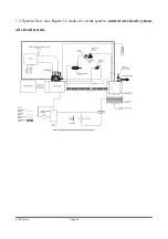
Page 12: ...LGCY Series Page 10 1 2 System flow see Figure 1 main air circuit system control air circuit system oil circuit system...

Page 13: ...charged into the air oil separator air oil tank and more than 99 of oil is separated Then after being further separated by the secondary oil air separator oil content core the clean compression air en...

Page 14: ...s the secondary oil air separator oil content core at a lower flow rate The residual lubricating oil is further separated through affinity coalescence method E Minimum Pressure Valve The clean separat...

Page 15: ...ted air release valve under the control of LOAD UNLOAD switching valve passage to make the oil air tank air and handpiece interconnected and reach internal circulating state The system is stabilized a...

Page 16: ...e the user needs to adjust the working pressure of the relevant proportional valve i e pressure regulator The adjustment procedure is as follows Step I turn the LOAD UNLOAD switching valve to or UNLOA...

Page 17: ...e output pressure and the output pressure decides the amount of expansion and contraction of two servo cylinders C Air intake valve servo cylinder The servo cylinder is the actuator The air intake val...

Page 18: ...t oil pump the lubricating oil relies on the pressure difference between the exhaust port of the compressor and the fuel injection port of the main engine to maintain the flow in the circuit When the...

Page 19: ...The misty oil contained in the compressed air can be almost completely filtered through the oil content core The oil particle size can be controlled to be less than 0 1um and the oil content can be l...

Page 20: ...aling and Conveying Process When the air intake is finished the tooth peak of male and female rotors will be sealed with enclosure The air in the intertooth space does not flow externally and this pro...

Page 21: ...rtooth space moves to the exhaust end face of the enclosure At this moment the intertooth space between the two rotor meshing surface and enclosure exhaust port is zero Then the exhaust process is com...

Page 22: ...d display 3 The use of advanced control technology providing stable and reliable operation of the compressor 4 Strong anti interference ability 5 Resistant to vibration high and low temperature humidi...

Page 23: ...racy 0 5 c Sensor 4 20mA high temperature pressure sensor 8 The oil filter clogging and generator testing 9 Loading and unloading control When the engine during normal operation a When the exhaust pre...

Page 24: ...Press to enter or exit the setting parameters of state or confirm the input parameters see parameter description b Shift eliminate In the parameter setting mode this button shift set different paramet...

Page 25: ...LGCY Series Page 23 8 Wiring diagram...

Page 26: ...r cooling Vertical type in line water cooling Air intake method Turbo Charged and Inter cooled Turbo Charged and Inter cooled Cylinder diameter stroke number of cylinders 116 5 148 6 116 5 148 6 Displ...

Page 27: ...ion is 15 1 2 If necessary put a wedge on the bottom to avoid displacement of the air compressor unit 1 3 To avoid dusty environment place the compressor in a place that is as clean as possible 1 4 Th...

Page 28: ...arator Open the drain valve at the bottom of oil air separator to discharge the condensate water during shutdown Once there is oil flowing out close the drain valve immediately 1 7 Check and clean the...

Page 29: ...le speed On the contrary gradually open the air supply ball valve After the pressure is reduced the speed of the diesel engine will be increased to the maximum speed to achieve the function of automat...

Page 30: ...l level is in the scope of view during start up and normal operation 4 6 The compressor must be monitored constantly during the test run In the future each instrument is inspected every 2 hours during...

Page 31: ...LGCY Series Page 29...

Page 32: ...pressure 2 Sudden stop of unit in use 1 Insufficient oil volume of fuel tank 2 Fuel pipeline air leakage 3 Fuel solenoid valve fault 4 Fuel filter clogging to cause insufficient oil supply 5 Diesel en...

Page 33: ...6 High oil consumption of compressor 1 Too high oil level 2 Lubricating oil specification error or failure 3 One way valve orifice blocking 4 Oil content core damage or failure 1 Check the oil level...

Page 34: ...LGCY Series Page 32 during stop...

Page 35: ...lter 2 Maintenance for First100 Running Hours 2 1 Unit 2 1 1 Clean the fuel tank and oil circuit 2 2 Diesel engine 2 2 1 Replace the diesel engine oil 2 2 2 Replace the diesel engine oil filter 2 2 3...

Page 36: ...Running Hours 6 1 Replace the compressor oil 7 Maintenance for Long term Stop The equipment shall be maintained as follows during long term stop particularly at the season or area with the temperature...

Page 37: ...ring the lifting equipment has sufficient capacity 8 2 When lifting it is not allowed to add heavy items in the unit which will cause the center of gravity of the unit to shift resulting in unbalanced...

Page 38: ...f compressor Replaced per 8000 hours or 11months YK3046A4W Z 2 Air filter main filter element of compressor Purged every day replaced per 500 hours YK3046A5 A 2 Air filter safety filter element of com...

Page 39: ...repare sufficient spare parts as described in the table in order to make the best use of compressor Contact Information HEAD OFFICE 134 140 Atlantic Drive Keysborough VIC 3173 AUSTRALIA Ph 61 3 8769 2...

Reviews: