background image

13

TILLER

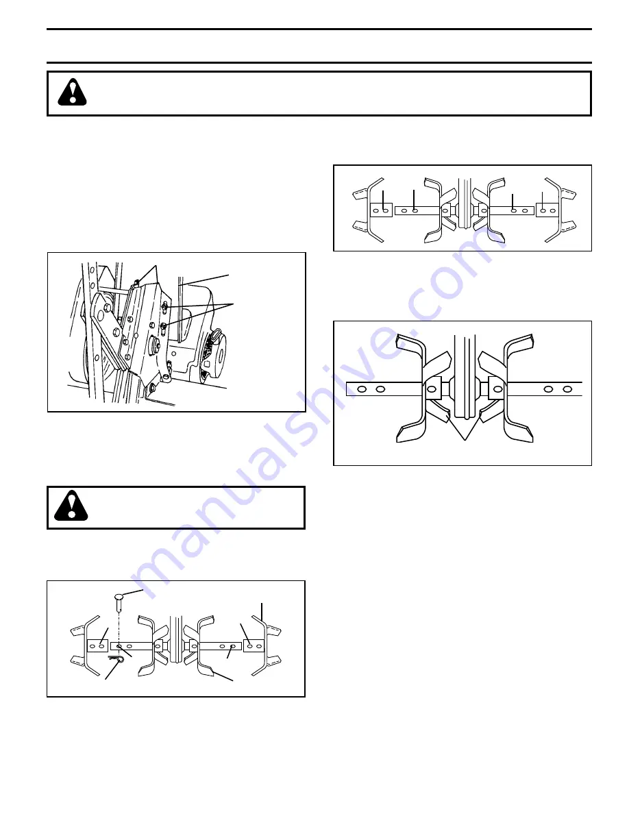
TO ADJUST HANDLE HEIGHT (See Fig. 15)

Factory assembly has provided lowest handle height.  Se lect 
handle height best suited for your tilling conditions.  Handle 
height will be different when tiller digs into soil.
•     If a higher handle height is desired, loosen the four 

nuts securing handle panel to engine brackets.

•      Slide handle panel to desired location.
•      Tighten the four nuts securely.

HANDLE
PANEL

ENGINE BRACKETS

NUTS (ALSO 2
ON LEFT SIDE
OF TILLER)

FIG. 15

SERVICE AND ADJUSTMENTS

CAUTION:  Disconnect spark plug wire from spark plug and place wire where it cannot come into 
contact with plug.

FIG. 16

FIG. 17

FIG. 18

TINE ARRANGEMENT

Your outer tines can be assembled in several different ways 
to suit your tilling or cultivating needs.

CAUTION:  Tines are sharp.  Wear 
gloves or other protection when han-
 dling tines.

NORMAL TILLING - 26" PATH (See Fig. 16) 

•     Assemble holes “A” in tine hubs to holes “B” in tine 

shaft.

tine_4

OUTER 
TINE

INNER TINE

HAIRPIN CLIP

A

B

A

B

CLEVIS
PIN 

MID-WIDTH TILLING - 24" PATH (See Fig. 17)

•     Assemble holes “A” in tine hubs to holes “C” in tine 

shaft.

tine_5

A

C

A

C

NARROW TILLING/CULTIVATING - 12-3/4" PATH  
(See Fig. 18)

•      Remove outer tines.

tine_6

INNER TINES  ONLY

NOTE:

  When reassembling outer tines, be sure right tine 

assembly (marked “R”) and left tine assembly (marked “L”) 
are mounted to correct side of tine shaft.

For Parts Call K&T 606-678-9623 or 606-561-4983

www.mymowerparts.com

Summary of Contents for 96082000200

Page 1: ...ANUAL MODEL NO SOF555 96082000200 5 5 HP 26 Inch Tiller For Parts and Service contact our authorized distributor call 1 800 849 1297 For Technical Assistance call 1 800 829 5886 For Parts Call K T 606...

Page 2: ...quipment without proper instruction Keep the area of operation clear of all persons par ticularly small children and pets PREPARATION Thoroughly inspect the area where the equipment is to be used and...

Page 3: ...IMPROVED FOREST COVERED BRUSH COVERED OR GRASS COVERED LAND UNLESS THE ENGINE S EXHAUST SYSTEM IS EQUIPPED WITH A SPARK ARRESTER MEETING APPLICABLE LOCAL LAWS IF ANY IF A SPARK ARRESTER IS USED IT SHO...

Page 4: ...rdware you assemble must be tightened securely Use the correct tools as necessary to insure proper tightness TOOLS REQUIRED FOR ASSEMBLY A socket wrench set will make assembly easier Standard wrench s...

Page 5: ...STAKE SPRING TILLER HANDLES 02 05 1 CABLE S FIG 2 handles_38 HANDLE PANEL BOLTS FLAT WASHER HEX BOLT 5 16 18X3 4 TILLER HANDLE HANDLE PANEL NUT LOCK WASHER HEX BOLT 5 16 18X1 ASSEMBLY HANDLE HEIGHT H...

Page 6: ...DEPTH STAKE TINE SHIELD CHOKE CONTROL FORWARD TINE CONTROL TINES THROTTLE CONTROL FIG 4 MEETS ANSI SAFETY REQUIREMENTS Our tillers conform to the safety standards of the American National Standards I...

Page 7: ...everse move ment ENGINE Move throttle control to STOP position Never use choke to stop engine TILLING The speed and depth of tilling is regulated by the position of the depth stake and wheel height Th...

Page 8: ...owly until engine reaches start of compression cycle rope will pull slightly harder at this point Pull recoil starter handle quickly Do not let starter handle snap back against starter If engine fires...

Page 9: ...essive bounce and difficult handling of your tiller Hard soil should be moistened before tilling however extremely wet soil will ball up or clump during tilling Wait until the soil is less wet in orde...

Page 10: ...NDATIONS The warranty on this tiller does not cover items that have beensubjectedtooperatorabuseornegligence Toreceive fullvaluefromthewarranty theoperatormustmaintaintiller as instructed in this manu...

Page 11: ...heck the crankcase oil level before starting the engine and after each five 5 hours of continuous use Add SAE 30 motor oil or equivalent Tighten oil filler plug securely each time you check the oil le...

Page 12: ...Replace spark plugs at the beginning of each tilling sea son or after every 50 hours of use whichever comes first Spark plug type and gap setting are shown in PRODUCT SPECIFICATIONS on page 3 of this...

Page 13: ...FIG 16 FIG 17 FIG 18 TINE ARRANGEMENT Your outer tines can be assembled in several different ways to suit your tilling or cultivating needs CAUTION Tines are sharp Wear gloves or other protection whe...

Page 14: ...V BELTS See Figs 21 and 22 Replace V belts if they have stretched considerably or if they show cracks or frayed edges There are two 2 V belts forward inside and reverse outside Belt guard must be rem...

Page 15: ...E TO ADJUST CARBURETOR Thecarburetorhasbeenpresetatthefactoryandadjustment should not be necessary However engine performance can be affected by differences in fuel temperature altitude or load If the...

Page 16: ...placement instructions in the Service and Adjustments section of this manual Lubricate as shown in the Maintenance section of this manual Be sure that all nuts bolts and screws are securely fastened I...

Page 17: ...l tank and refill with fresh gasoline 7 Water in fuel 7 Empty fuel tank and carburetor and refill tank with fresh gasoline 8 Clogged fuel tank 8 Remove fuel tank and clean 9 Spark plug wire loose 9 Co...

Page 18: ...d This Warranty does not apply to any product which has been subjected to alteration misuse abuse improper assembly or installation delivery damage or to normal wear of the product 5 Exclusions Exclud...

Reviews: