Page 20 of 26
Installation & Adjustment Procedures
•
Re-tighten the Adjustable Arm and Clevis Clamping Bolts.
•
Test Operate. Re-adjust as necessary.
5. All poles of the fully adjusted switch should close completely and operate
together. Slight adjustment of the Hinge Assembly Clamping Bolts may be
necessary to coordinate all three poles. Rapid operation of the manual handle
may be necessary to achieve full closing of all three poles.
6. No adjustment of the Grounding Switch Blade closest to the Operating Arm is
necessary.
7. The Grounding Switch Blade on the remaining two poles will require “lead” (Blade
movement in advance of the Blade on the pole closest to the Operating Arm):
•
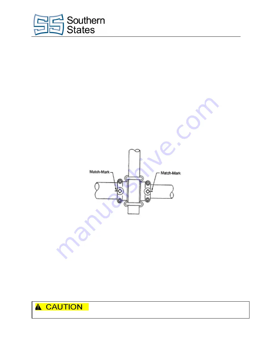
With the Grounding Switch in the open position, match-mark the Hinge
Clamp and pipe.
•
Adjust “lead” by elevating the Blade slightly -
Figure 11: Match-Marked Hinge Clamp and Pipe
•
Be sure the Blade Tip rests against the Blade Stop when the Blade is in the
closed position.
•
Test Operate. Re-adjust as necessary.
8. When the switch is fully adjusted:
•
Pre-drill pipe for setscrews with the Threaded Drill Guides supplied and a ¼”
drill.
•
Securely tighten all bolts.
•
Tighten setscrews until pipe wall is pierced -
Penetrate the aluminum pipe only with setscrews. Forcing
setscrews into the steel pipe can result in casting breakage.
Summary of Contents for CBL-T
Page 2: ...Page II The Quality Name in High Voltage Switching ...
Page 3: ...Page III The Quality Name in High Voltage Switching Safety Information ...
Page 6: ...Page VI The Quality Name in High Voltage Switching ...
Page 7: ...Page VII The Quality Name in High Voltage Switching Type CBL T ...
Page 25: ...Page 21 of 26 Installation Adjustment Procedures Figure 12 Piercing Pipe Wall ...
Page 31: ......


