background image

16

SERVICE  AND ADJUSTMENTS

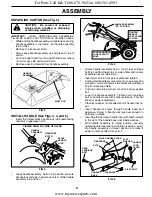
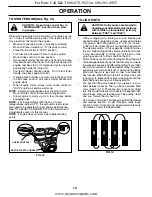
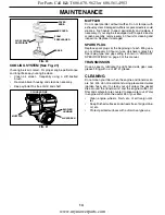
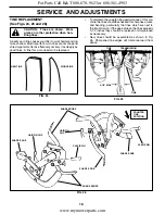
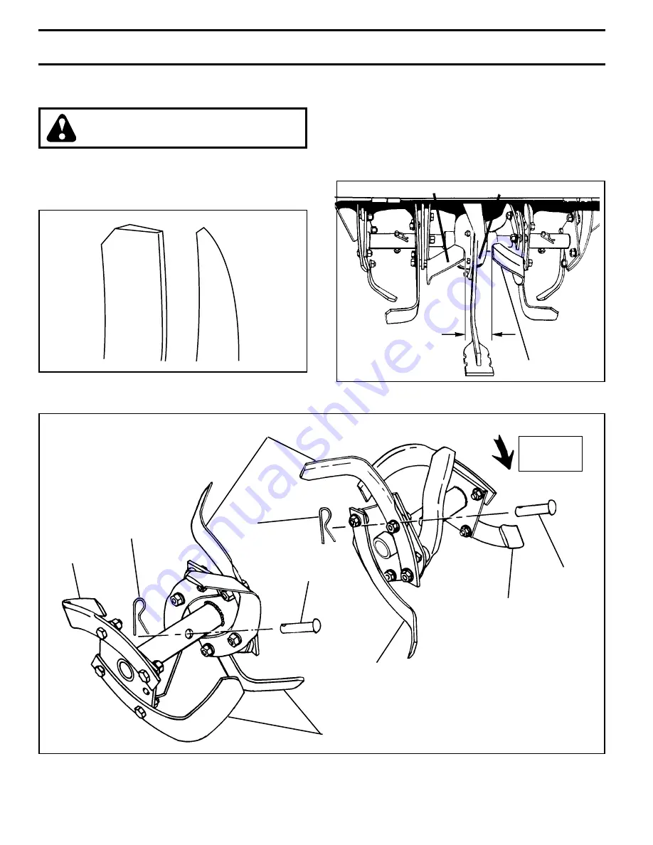
FIG. 26

FIG. 25

FIG. 24

•      To maintain the superb tilling performance of this ma-

 chine the tines should be checked for sharpness, wear, 
and bending, particularly the tines which are next to 
the transmission.  If the gap between the tines ex ceeds 
3-1/2 inches they should be replaced or straight ened 
as necessary.

•     New tines should be assembled as shown in Fig. 

26.  Sharp ened tine edges will rotate rearward from 
above.

TINE REPLACEMENT 
(See Figs. 24, 25 and 26)

CAUTION:  Tines are sharp.  Wear 
gloves or other protection when han-
 dling tines.

A badly worn tine causes your tiller to work harder and dig 
more shallow.  Most important, worn tines cannot chop and 
shred organic matter as effectively nor bury it as deeply as 
good tines.  A tine this worn needs to be replaced.

NEW TINE

WORN TINE

3-1/2" MAX

TINE

TINE

TRANSMISSION

COUNTER
TINE
ROTATION

HAIRPIN 
CLIP

HAIRPIN CLIP

       CLEVIS PIN

CLEVIS PIN

SHARP EDGE

SHARP EDGES

SHARP EDGES

SHARP  EDGE

SHARP EDGE

For Parts Call K&T 606-678-9623 or 606-561-4983

www.mymowerparts.com

Summary of Contents for SOR900A

Page 1: ...orage Troubleshooting Repair Parts OWNER S MANUAL MODEL NO SOR900A 9 HP 21 Inch Tiller For Parts and Service contact our authorized distributor call 1 800 849 1297 For Technical Assistance call 1 800...

Page 2: ...controls quickly Never allow children to operate the equipment Never allow adults to operate the equipment without proper instruction Keep the area of operation clear of all persons par ticularly smal...

Page 3: ...ved forest covered brush covered or grass covered land un less the engine s exhaust system is equipped with a spark arrester meeting applicable local or state laws if any If a spark arrester is used i...

Page 4: ...ket wrench set will make assembly easier Standard wrench sizes are listed 1 Utility knife 1 Tire pressure gauge 1 Pair of pliers 1 9 16 wrench OPERATOR S POSITION See Fig 1 When right or left hand is...

Page 5: ...sembly in lowest position securely tighten handle lock lever by rotating clockwise Leav ing handle assembly in lowest position will make it easier to remove tiller from carton UNPACKING CARTON See Fig...

Page 6: ...for best tilling performance Reduce tire pressure to 20 PSI 1 4 kg cm2 HANDLE HEIGHT Handle height may be adjusted to better suit operator See TO ADJUST HANDLE HEIGHT in the Service and Adjustments s...

Page 7: ...VER OUTER SIDE SHIELD FIG 8 MEETS ANSI SAFETY REQUIREMENTS Our tillers conform to the safety standards of the American National Standards Institute SHIFT LEVER Used to shift transmission gears SHIFT L...

Page 8: ...edrivecontrolbarandreleaseorrocktiller forward and backward until are able to shift gears DEPTH STAKE See Fig 10 The depth stake can be raised or lowered to allow you more versatile tilling and cultiv...

Page 9: ...DIRT TO ENTER THE ENGINE WHEN CHECKING OR ADDING OIL OR FUEL USE CLEAN OIL AND FUEL AND STORE IN APPROVED CLEAN COVERED CONTAINERS USE CLEAN FILL FUNNELS CHECK ENGINE OIL LEVEL See Fig 12 The engine...

Page 10: ...weight off the wheels and reduces traction To get through a really tough section of sod or hard ground apply upward pressure on handle or lower the depth stake TO START ENGINE See Fig 13 CAUTION Keep...

Page 11: ...with shear pins See TINE REPLACEMENT in the Service and Adjustments section of this manual If the tiller is unusually overloaded or jammed the shear pins are designed to break before internal damage...

Page 12: ...ners LUBRICATION Keep unit well lubricated See LUBRICATION CHART MAINTENANCE SCHEDULE FILL IN DATES AS YOU COMPLETE REGULAR SERVICE Check Engine Oil Level Change Engine Oil Oil Pivot Points Inspect Ai...

Page 13: ...nning low on oil Change the oil after every 25 hours of operation or at least once a year if the tiller is not used for 25 hours in one year Check the crankcase oil level before starting the engine an...

Page 14: ...1 COOLING SYSTEM See Fig 21 Your engine is air cooled For proper engine performance and long life keep your engine clean Clean air screen frequently using a stiff bristled brush Remove blower housing...

Page 15: ...plug HANDLE LOCK LEVER TIRE CARE CAUTION When mounting tires un lessbeadsareseated overinflationcan cause an explosion Maintain 20 pounds of tire pressure If tire pressures are not equal tiller will...

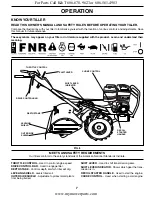
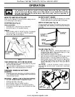
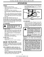
Page 16: ...rearward from above TINE REPLACEMENT See Figs 24 25 and 26 CAUTION Tines are sharp Wear gloves or other protection when han dling tines A badly worn tine causes your tiller to work harder and dig mor...

Page 17: ...in groove of transmission pulley and into engine pulley BELT MUST BE IN GROOVE ON TOP OF IDLER PULLEY NOTE POSITION OF BELT TO GUIDES Check belt adjustment as described below Replace belt guard Repos...

Page 18: ...gh speed stop and hold in this position Tighten cable clamp screw securely TO ADJUST CARBURETOR Thecarburetorhasbeenpresetatthefactoryandadjustment should not be necessary However engine performance c...

Page 19: ...until the fuel lines and carburetor are empty Never use engine or carburetor cleaner products in the fuel tank or permanent damage may occur Use fresh fuel next season NOTE Fuel stabilizer is an accep...

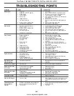
Page 20: ...e loose 9 Connect and tighten spark plug wire 10 Dirty engine air screen 10 Clean engine air screen 11 Dirty clogged muffler 11 Clean replace muffler 12 Carburetor out of adjustment 12 Make necessary...

Page 21: ...ntrol KEY PART NO NO DESCRIPTION 1 180638 Control Throttle 2 9266R Grip Handle 4 159228 Bar Assembly Control 6 180678 Panel Control 8 71191008 Screw Truss Hd 10 24 Unc x 1 2 10 8206H Grip Handle 11 44...

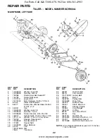
Page 22: ...0600 Washer Lock 3 8 3 73220600 Nut Hex 3 8 16 4 180046 Shield Inner Belt Guard RT 5 154734 Screw Shift Lever 6 110111X Lever Shift 7 72110404 Bolt Carriage 1 4 20 x 1 2 Gr 5 8 8700J Plate Shift Indic...

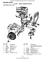
Page 23: ...8 x 2 22 74760524 Bolt Hex Hd 5 16 18 x 1 1 2 1 175624 Bumper 7 180275 Counter Weight R H 8 10040600 Washer Lock 3 8 9 73220600 Nut Hex 3 8 16 11 4921H Clip Hairpin 12 4929H Rivet Drilled 13 5015J Tir...

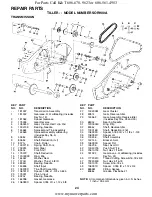
Page 24: ...18 48 100107K Screw 5 16 18 x 4 49 106391X Spacer 0 765 ID x 1 12 x 3 4 60 6855M Fitting Grease 6066J Grease Plastilube 1 181337 Transmission Assembly 1 181332 Gearcase R H w Bearing Includes Key No 1...

Page 25: ...1 4 KEY PART NO NO DESCRIPTION 1 73900500 Nut Lock Hex Flange 5 16 18 2 161416X417 Shield Side Outer L H 3 8393J Pin Stake Depth 4 12000035 Ring Klip 5 72140508 Bolt Carriage 5 16 18 Unc x 1 6 8394J S...

Page 26: ...45L Assembly Hub and Plate 6 73610600 Nut Hex 3 8 24 7 10040600 Washer Lock 3 8 KEY PART NO NO DESCRIPTION 8 74610616 Bolt Hex 3 8 24 x 1 9 6557J Tine Outer R H 12 74610624 Bolt H 3 8 24 x 1 1 2 13 49...

Page 27: ...3 186250 Decal Tine Shield CRT 4 162215 Decal Tine Shield Warning 5 141907 Decal Hand Placement 6 138546 Decal Shift Indicator 7 141906 Decal Warning 8 186300 Decal Engine 9 186247 Decal Control Pane...

Page 28: ...02716 Southern States For Parts Call K T 606 678 9623 or 606 561 4983 www mymowerparts com...

Reviews: