background image


24 

Summary of Contents for Graphic Whizard PT320 CC

Page 1: ...PT320 CC Business card cutter SET UP OPERATOR S MANUAL 755 Griffith Court Burlington Ontario CANADA Tel 905 633 7663 Fax 905 637 4419 WWW GRAPHICWHIZARD COM 1...

Page 2: ...rameters 7 1 3 Accessories 7 1 4 Machines Diagram 8 Chapter 3 Set up operation and maintenance 9 1 Set up 9 1 1 Set up Guide 9 1 2 Set up Guidelines 10 2 Operation 11 2 1 Cutting 11 2 2 Operation Pane...

Page 3: ...er Jamming 38 3 3 Long Blade Jam 39 3 4 Cut Mark not detected 39 3 5 Cut Mark Sensor failed 40 3 6 Paper Size 40 3 7 Paper Feeding 41 4 Aftercare 42 4 1 Maintenance 4 2 Machine Parts Lifespan 42 5 Sys...

Page 4: ...oduct line Please note The design and specifications of this machine are subject to change without notice and without our legal obligation All rights are reserved No part of this manual may be photoco...

Page 5: ...erator is aware of all safety features and possible hazards on the machine 2 1 Operational Safety Guidelines Both fixing and lock covers are set to prevent any tools and clothes from being rolled into...

Page 6: ...ing right away 2 1 2 Lock cover fixing cover Upper cover Switch for lock cover Left side cover Right side cover Front cover Fig 1 1Front Fig 1 2 Top Fig 1 3 Back Safety Labels Take care pinch point Ta...

Page 7: ...3 320 450mm 12 x 18 Paper thickness 0 20mm 180g m 0 35mm 350g m Cutting speed 250 business cards in under 2 minutes Cutting size Longitudinal 89 85 90 95 mm Horizontal 45 50 54 90 95 127 mm 40 250mm c...

Page 8: ...eeding wheel 7 Power switch 8 Frontal cover 9 Power cord 10 Lock nut 11 Paper weight adjustment needle 12 Paper weight adjustment needle 13 Left paper guide plate 14 Right paper guide plate 15 Paper f...

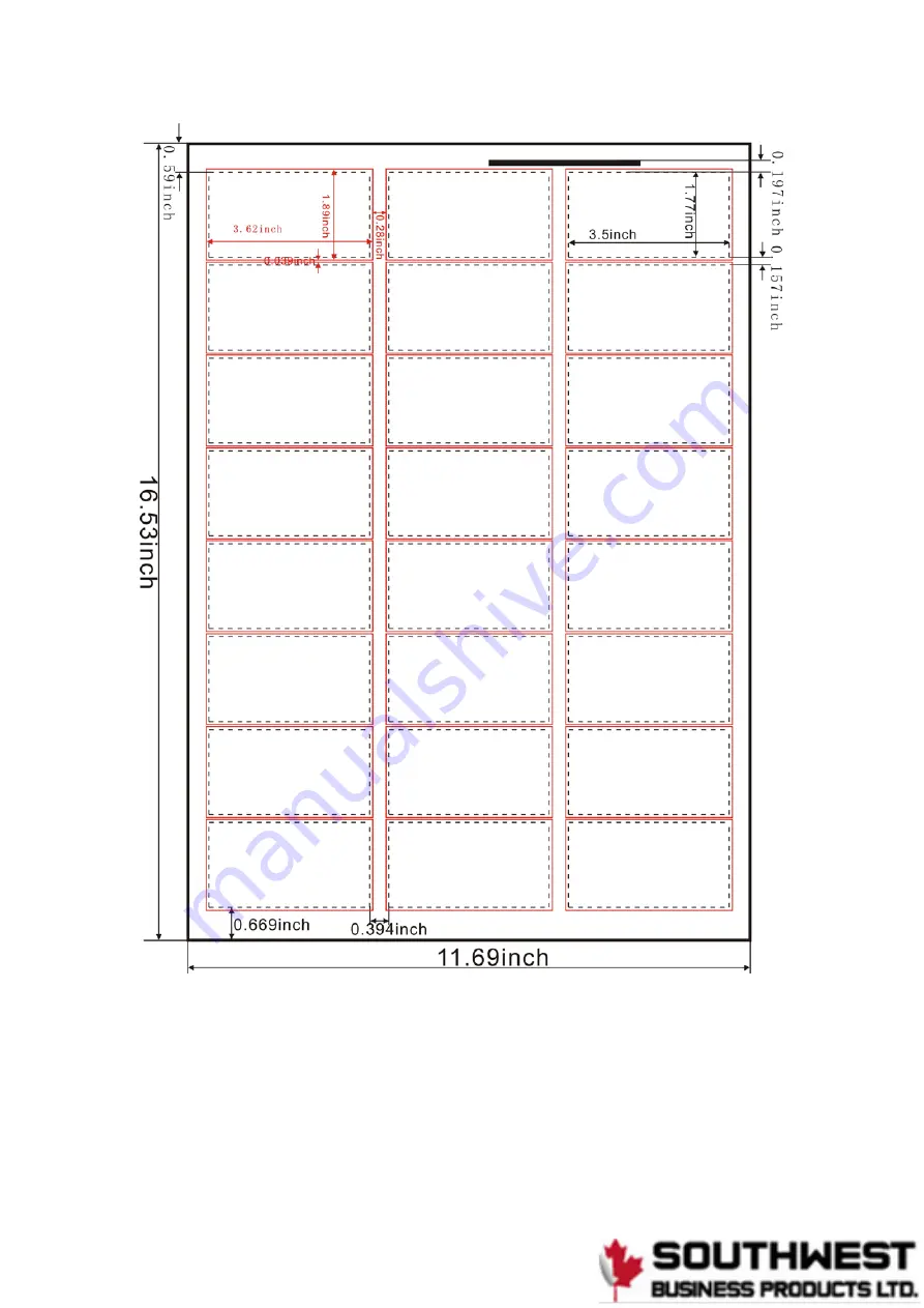
Page 9: ...been set up to accept 12X18 sheets The actual measurements for this setting is 12 59 X 17 71 which is well within the capabilities of the 320CC 3 50X2 00 defines the size of the cut cards in the curr...

Page 10: ...e selected mode will program the default parameters Some changes should not be required Cut Pieces this is defined by the Mode In this instance the 320CC is set to cut 24 pieces This number increases...

Page 11: ...n first cut compensation When setting the 320CC to cut for the first time set the compensation for 0 000 and make changes only if needed This permits the user to adjust the position of the first cut C...

Page 12: ...to cut for the first time set the compensation for 0 000 and make changes only if needed Sub accumulated cards 2265 current subtotal of cards cut per current job This parameter can be cleared by pres...

Page 13: ...ut This parameter is for information only Sheet size A3 or SRA3 displays the current sheet size Note though the option is defined as SRA3 the 320CC has been set up for North American parameters This p...

Page 14: ...create the best cut for your business cards Paper alignment slitter cut The slitters are fixed in the 320CC and should not require adjusting Before making any electronic adjustments ensure your cut m...

Page 15: ...d Note the numbers below show centre maximum and minimum variance of the first cut from the leading edge This parameter is not used with the registration mark First cut at 0 000 0 3410 inches First cu...

Page 16: ...to zero The above image shows the results of the first cut with parameters set to zero A close up shot shows only 7 cards were cut The 8th card ended up as waste To fix this we will have to adjust th...

Page 17: ...table working table 3 Insert the business card catcher on the back of the machine then place it flatly Insert it completely and ensure contact with the magnetic switch 4 Make the ground wire is ground...

Page 18: ...ensure the machine is clear of the following Direct sunshine Mists Moisture wetness In an area with frequent temperature changes Areas which may be consistently vibrating Please do not use any other...

Page 19: ...ove once place the printing test used paper on the paper feed desk Paper selection A3 Cutting mode selection xx 50 mm xx 54 mm xx 95 mm Adjust the left right positions of the paper feed desk cut the t...

Page 20: ...the cutting size adjustment Stop key stop cutting during a job decrease the value in the cutting size adjustment LCD screen display the cutting mode and counting 2 LCD display After the power is turn...

Page 21: ...s the datum for cutting OR 2 Mark take the pre printed mark as the datum for cutting 2 3 2 Printing condition with the paper mark The set pieces to be cut Separate cumulation The selected cutting mode...

Page 22: ...4 cards 89 50mm use C 3 89 rotating cutter group 3 columns 7 rows total 21 cards 89 54mm use C 3 89 rotating cutter group 3 columns 7 rows total 21 cards 89 90mm use C 3 89 rotating cutter group 3 col...

Page 23: ...t a sheet with all parameters settings at 0 and go from there INSTRUCTIONS 1 Turn on power 2 Press Mode Changeover button until LCD screen reads 3 5x2 3 Press Set Parameter button Select number of car...

Page 24: ...ctory settings a Press to initiate will have to then turn off machine 10 Press Set Parameter to choose measurement method a Use to change between inches and mm 11 Press Set Parameter returned to idle...

Page 25: ...17...

Page 26: ...A3 420 297 88 9mm 45mm 18...

Page 27: ...A3 420 297 88 9mm 50mm 19...

Page 28: ...A3 420 297 88 9mm 54mm 20...

Page 29: ...A3 420 297 88 9mm 50 8mm 21...

Page 30: ...A3 420 297 88 9mm 95mm 22...

Page 31: ...A3 420 297 88 9mm 127mm 23...

Page 32: ...24...

Page 33: ...25...

Page 34: ...26...

Page 35: ...27...

Page 36: ...28...

Page 37: ...88 9mm 40 250 mm customize 29...

Page 38: ...the Parameter setting key the LCD displays Adjust it via or key Press the Mode changeover key to return to the standby state 2 5 2 Datum selection Continue pressing the Parameter setting key till the...

Page 39: ...ng key till the LCD displays Press the key to reset the separate counting of the cut pieces Press the Mode changeover key to return to the standby state 2 5 6 Adjust the business card size Continue pr...

Page 40: ...turn to the standby state 2 5 9 Recover the ex works setting Continue pressing the Parameter setting key till the LCD displays Press key to recover the ex works setting or the Mode changeover key to g...

Page 41: ...angeover key to return to the standby state the size error adjustment ends Press Mode changeover key to return to the standby state the size error adjustment ends Press Parameter setting key again the...

Page 42: ...ore than 1 second for faster adjustment Press Parameter setting key until the LCD displays Adjust it via or key Press Parameter setting key until the LCD displays Adjust it via or key Press the Mode c...

Page 43: ...stock without curl into the machine d Do not place papers of different kinds coated and non coated etc at the same time or paper feeding may be affected e Do not use plastic sealed paper film coated...

Page 44: ...turn off the power when not in use 2 7 Replacing the longitudinal knife assembly 2 7 1 Please follow the guide below when taking out the knife assembly Make sure the power to the machine is cut off to...

Page 45: ...r Turn on the power and see if there is an abnormal sound oblong hole gears screw 2 8 Paper thickness adjustment When shipped the thickness adjustment needle points to the middle which is set for an a...

Page 46: ...ien will also default to a stop position or back to the standby state 3 1 Safety cover fails If the top cover is off there will be buzzer sound Correction Turn off the power put on the top cover secur...

Page 47: ...hick the stock is curled When the LCD shows Long blade jam Press Mode changeover the LCD will show Press Parameter setting key and select or key to settle the problem Press Mode changeover to EXIT Pre...

Page 48: ...mode non white paper is used When the LCD shows Mark sensor failed Press Mode changeover the LCD will show Press Parameter setting key and select or key to settle the problem Press Mode changeover to...

Page 49: ...A The paper guide plate is set too tightly use the micro adjusting nut to readjust it B Paper feeding problems may also occur with improper paper Please conform to the following Too thick over 0 35mm...

Page 50: ...on plate on the back of the machine Rotary Blade direction Switch on the power open the machine Voltage range 90v 260v Spread the paper tray dividers Move the paperboard to match the paper size Revolv...

Page 51: ...choose the sign position compensation according to the above method of operation D When the cards corner is not at a right angle We shall change the Rotary blade s place Method Switch off the power t...

Page 52: ...fixed screws At last pull out the wire Setting up set up the fixed screws eccentric wheel triangle travel switch and motor fixed frame motor shield successfully Then insert the wire 5 Stripper pad exc...

Page 53: ...o make sure the triangle iron is matching the groove and in more than two thirds 6 When the long blade is working but the paper cannot cut and the boundary shows fail cutting it s because that the pap...

Reviews: