background image

13 

GAS LINE INSTALLATION 

 
GAS  LINE  HOOK UP  SHOULD  BE  DONE  BY  YOUR  GAS  SUPPLIER  OR  A  QUALIFIED  SERVICE 
PERSON. 


NOTE: BEFORE YOU PROCEED, BE SURE YOUR GAS SUPPLY IS OFF! 

 
A  gas line  may  be  installed for use  with  a 

decorative  gas  appliance, 

available 

through your local distributor. Use only 

1/2 inch

 black iron pipe and appropriate 

fittings. When installing a gas line, a shut off valve designed for installation out-
side the fireplace is recommended. 
 
Installation procedure: 
 
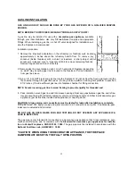
1.  Remove  the  knockout  indentation  on  the  refractory  (or  firebrick)  wall,  located 

approximately  2  inches  above  the  refractory  hearth  floor.  To  remove,  pry 
knockout  (inside  fireplace)  with  a  chisel,  screwdriver  or  sharp  object  until 
knockout is re-leased. Use ¾ “ masonry drill bit to remove remaining firebrick. 
Remove fragmented portion of refractory. 

 
2. Remove gas line cover plane on right  or left hand side of fireplace (depending 

on which way incoming gas line is routed to the fireplace). Pull out insulation 
from gas line sleeve. 

 
3. Run a 1/2 inch NPT black iron gas line into the fireplace 8 1/2 inches from the floor, and route into the 

fire chamber through the gas line sleeve. (If using a raised platform, add height of platform to specified 
8 1/2 inches.) Provide sufficient gas line into fireplace chamber for fitting connection. 


NOTE: Secure incoming gas line to wood framing to pro-vide rigidity for threaded end.


4.  Pack insulation around gas line and into sleeve openings. Seal any gaps between gas line and refrac-

tory knockout hole with refractory cement or commer-cial furnace cement. Either install decorative gas 
ap-pliance (per instructions included with appliance) or cap off gas line. 


CAUTION

:  

All gas piping and connections must be tested for leaks after installation is complete.


With gas turned ON, apply a soap and water solu-tion to all connections and joints. If bubbles ap-pear, 
leaks can be detected and corrected. 

 
DO NOT USE  AN  OPEN FLAME FOR LEAK TEST-ING. DO NOT OPERATE  ANY  APPLIANCE IF A 
LEAK IS DETECTED. 

 
The gas pipe is only intended for connection to a decora-tive gas appliance that 1) incorporates an auto-
matic shut off device, and 2) complies with the 

Standard for  decorative gas appliances for Installa-

tion in Vented Fireplaces, ANSI Z21.60 1 990. 

The gas pipe must be installed in accordance with the 

National Fuel Gas code, ANSI Z223.1 1992. 
 

“CAUTION” WHEN USING THE DECORATIVE APPLIANCE, THE FIREPLACE 
DAMPER MUST BE SET IN THE FULLY OPEN POSITION 

Summary of Contents for Kiva SWK24

Page 1: ...tractor or an installer certified by Southwest KIVA Inc Any permits required for installation should be obtained by contractor as well as any other construction industry inspections that may be requir...

Page 2: ...ystem 6 IV Chimney Installation 7 V Frame Installation 11 VI Door Frame Installation 11 VII Finishing Plastering the Fireplace 12 VIII Gas Pipe Installation 12 Parts List and Options 13 2 ALL PICTURES...

Page 3: ...doors 3 A location where the cutting of joists or roof rafters can be avoided 4 The required outside air kit can be easily installed See Page 6 II FIREBOX INSTALLATION When installing the firebox it...

Page 4: ...See Figure 3 To place the front of firebox bottom section make a mark on the centerline out from the corner according to Chart A Row D example Laguna 32 With a carpenter s square draw a perpendicular...

Page 5: ...the bottom section along the brick curve outlining the curve Remove the center section and spread refractory mortar 1 behind the line drawn on the bottom section Reset the center section press into po...

Page 6: ...n the frame area Using the sleeve of the vent as a template draw a 6 circle on the wall cut out the circle and insert the vent Secure the out side of the vent to the wall using 4 8 x 1 1 2 hex head se...

Page 7: ...construction needs to be 24 above the roof height parapet wall or roof peak The appropriate roof flashing should be secured to the top of the chase Note Any roof or floor decking should not cover any...

Page 8: ...il hem seats The outer section can now be installed Press down on outer section until the lances on the lower end securely engage and snap into the fireplace starting collar The wire spacer will assur...

Page 9: ...igure 16 6 Once the pipe run is complete install the flashing either secured to the roof or top of chase over the protruding pipe Next install the storm col lar around the exterior of the flue section...

Page 10: ...turn elbow Straps must be securely nailed to rafters joists or studs 3 Maximum lengths of pipe between supports return elbow or 12S 8DM is 6 of angled run Maximum of two 6 angled run sections per chim...

Page 11: ...with 6 x1 2 self drilling screws Once in place the mesh should be folded down on top of the hearth banco This mesh is also screwed to the frame with 6 x1 2 self drilling screws when the fireplace fram...

Page 12: ...ISHING PLASTERING THE FIREPLACE First plaster the interior of the kiva opening arch with a mortar mix of 1 part Portland cement 1 2 part lime 3 parts Vermiculite 1 2 cup by vol of shredded fiberglass...

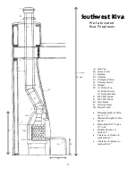
Page 13: ...ugh the gas line sleeve If using a raised platform add height of platform to specified 8 1 2 inches Provide sufficient gas line into fireplace chamber for fitting connection NOTE Secure incoming gas l...

Page 14: ...ator Superior and Temco Firestop Spacer Flashing Chimney 12 18 24 36 48 Rain Cap Storm Collar 30 Degree offset FIREPLACE ACESSORIES Door Frame Part DF24 Outside Air OAK24 Damper Plate DP24 Chimney Sta...

Page 15: ...ock K Steel Frame L Firestop Spacer M Plaster Finish Minimum height of chim ney 11 1 2 Maximum height of chim ney 50 Banco Hearth 18 high x 18 wide Height of firebox w blocks 43 Clearance of Firebox t...

Reviews: