background image

III. COMBUSTABLE AIR SYSTEM: MUST BE INSTALLED 


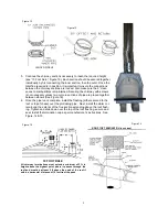
Your accessory kit includes an outside combustion duct Part #OAK


vent 

(Figure 7)

.  


Installation of the combustion air system can be installed at the same time as the roof flashing.  
The function of this installation is to provide an additional oxygen source to the firebox and air cooled chim-
ney.  If the firebox shares an exterior wall (where the vent can be placed directly out the wall), proceed to 
paragraph A for installation procedures.  If the firebox does not have exterior wall access, proceed to para-
graph B for installation procedures.  The combustion air system cannot terminate in attic space. 
 

A.  EXTERIOR WALL INSTALLATION 

The air vent (part #OAK) should be placed at least 12” above the floor on the exterior wall.  If both walls have 
outside access, either may be used.  

The air vent must be placed with in the frame area

.  Using the sleeve 

of the vent as a template, draw a 6” circle on the wall, cut out the circle, and insert the vent.  Secure the out-
side of the vent to the wall using (4) #8 x 1 1/2”  hex head self-drilling screws.  
 

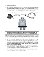
B.  INTERIOR WALL INSTALLATION (Figure 8) 

If an exterior wall is not available, the air vent must be installed on the outside of the chimney chase, between 
the roof and the flashing, using 6” flex aluminum duct (not provided) down to the firebox area.  Using the 
sleeve of the air vent as a template, draw a 6” circle on the chase, cut out the circle, and insert the vent.   
Secure the outside of the vent to the chase using (4) #8 x 1 1/2”  hex head self-drilling screws.   Inside the 
chase, attach the 6”  flex aluminum duct to the air vent sleeve, secure with screws, and stretch flex vent along 
chimney pipe run down to the area directly behind the firebox.  See Page 7 for minimum chase dimensions.


Part #OAK 


2” Clearance 
between chimney 
& studs 


Part #OAK 

Figure 7 

Figure 8 


Roof 

6” Flex extended to area behind firebox 

Flashing 

Storm Collar 

Termination Cap 


Summary of Contents for Kiva SWK24

Page 1: ...tractor or an installer certified by Southwest KIVA Inc Any permits required for installation should be obtained by contractor as well as any other construction industry inspections that may be requir...

Page 2: ...ystem 6 IV Chimney Installation 7 V Frame Installation 11 VI Door Frame Installation 11 VII Finishing Plastering the Fireplace 12 VIII Gas Pipe Installation 12 Parts List and Options 13 2 ALL PICTURES...

Page 3: ...doors 3 A location where the cutting of joists or roof rafters can be avoided 4 The required outside air kit can be easily installed See Page 6 II FIREBOX INSTALLATION When installing the firebox it...

Page 4: ...See Figure 3 To place the front of firebox bottom section make a mark on the centerline out from the corner according to Chart A Row D example Laguna 32 With a carpenter s square draw a perpendicular...

Page 5: ...the bottom section along the brick curve outlining the curve Remove the center section and spread refractory mortar 1 behind the line drawn on the bottom section Reset the center section press into po...

Page 6: ...n the frame area Using the sleeve of the vent as a template draw a 6 circle on the wall cut out the circle and insert the vent Secure the out side of the vent to the wall using 4 8 x 1 1 2 hex head se...

Page 7: ...construction needs to be 24 above the roof height parapet wall or roof peak The appropriate roof flashing should be secured to the top of the chase Note Any roof or floor decking should not cover any...

Page 8: ...il hem seats The outer section can now be installed Press down on outer section until the lances on the lower end securely engage and snap into the fireplace starting collar The wire spacer will assur...

Page 9: ...igure 16 6 Once the pipe run is complete install the flashing either secured to the roof or top of chase over the protruding pipe Next install the storm col lar around the exterior of the flue section...

Page 10: ...turn elbow Straps must be securely nailed to rafters joists or studs 3 Maximum lengths of pipe between supports return elbow or 12S 8DM is 6 of angled run Maximum of two 6 angled run sections per chim...

Page 11: ...with 6 x1 2 self drilling screws Once in place the mesh should be folded down on top of the hearth banco This mesh is also screwed to the frame with 6 x1 2 self drilling screws when the fireplace fram...

Page 12: ...ISHING PLASTERING THE FIREPLACE First plaster the interior of the kiva opening arch with a mortar mix of 1 part Portland cement 1 2 part lime 3 parts Vermiculite 1 2 cup by vol of shredded fiberglass...

Page 13: ...ugh the gas line sleeve If using a raised platform add height of platform to specified 8 1 2 inches Provide sufficient gas line into fireplace chamber for fitting connection NOTE Secure incoming gas l...

Page 14: ...ator Superior and Temco Firestop Spacer Flashing Chimney 12 18 24 36 48 Rain Cap Storm Collar 30 Degree offset FIREPLACE ACESSORIES Door Frame Part DF24 Outside Air OAK24 Damper Plate DP24 Chimney Sta...

Page 15: ...ock K Steel Frame L Firestop Spacer M Plaster Finish Minimum height of chim ney 11 1 2 Maximum height of chim ney 50 Banco Hearth 18 high x 18 wide Height of firebox w blocks 43 Clearance of Firebox t...

Reviews: