background image

n  m VA F M k

AUTO  HOLD   MAX  MIN   REL   LOZ

0

10

20

30

40

n  m VA F M k

AUTO  HOLD   MAX  MIN   REL   LOZ

0

10

20

30

40

n  m VA F M k

AUTO  HOLD   MAX  MIN   REL   LOZ

0

10

20

30

40

-

+

11

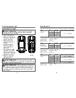
Operation cont.

1. Set the rotary function switch to 

    the 

10A

 position.

2. Insert the black test lead into the 


COM

 input jack and the red test 

    lead into the 

10A

 input jack. 

3. Remove power from the circuit 

    under test, then open up the 

    circuit at the point where you 

    wish to measure current.

4. Touch the test lead probes in 

    series with the circuit being 

    measured. Touch the red probe 

    to the positive side of the circuit 

    and touch the black probe to the 

    negative side of the circuit.

5. Apply power to the circuit.

6. Read the current on the LCD display.

DC Current Measurements

   Observe all safety precautions when 

working on live circuits. Do not measure current on circuits 

that exceed 600V. Measurements in the 10A range should 

be limited to 30 seconds maximum every 15 minutes.

WARNING:

12

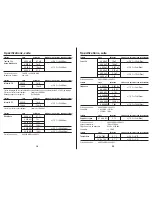
Operation cont.

1. Set the rotary function switch to 

    the 

HZ %

 position.

2. Press the MODE button to select 

    frequency or 

%

 duty cycle. The 

    “

Hz

” or “

%

” symbol will appear 

    on the LCD display. 

3. Insert the black test lead into the 


COM

 input jack and the red test 

    lead into the 

V

 input jack.

4. Touch the test lead probes to the 

    circuit under test.

5. Read the frequency or

 %

 duty cycle 

    on the LCD display.

Frequency and % Duty Cycle Measurements

   Observe all safety precautions 

when working on live voltages.

WARNING:  

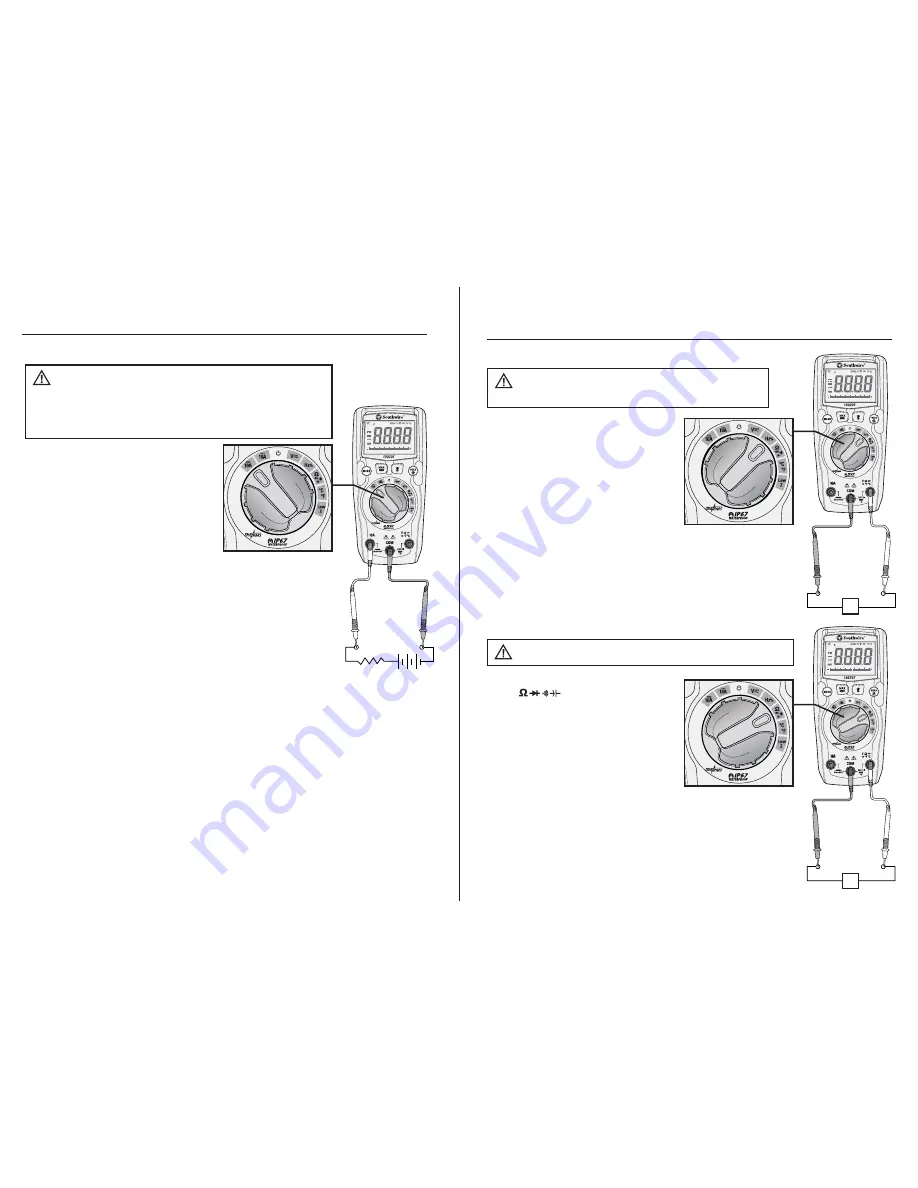
1. Set the rotary function switch to 

    the 


position.

2. Press the 

MOD

E button until the 

    “

Ω

” symbol appears on the LCD 

    display. 
3. Insert the black test lead into the 


COM

 input jack and the red test 

    lead into the 

Ω

 input jack.

4. Touch the test lead probes to the component under 

    test. If the component is installed in a circuit, it is 

    best to disconnect one side before testing to eliminate 

    interference with other devices.
5. Read the resistance in on the LCD display

Resistance Measurements

   Never test resistance on a live circuit  

WARNING:  

Hz

Ω

n  m VA F M k

AUTO  HOLD   MAX  MIN   REL   LOZ

0

10

20

30

40

n  m VA F M k

AUTO  HOLD   MAX  MIN   REL   LOZ

0

10

20

30

40

n  m VA F M k

AUTO  HOLD   MAX  MIN   REL   LOZ

0

10

20

30

40

Summary of Contents for 13070T

Page 1: ... CURITÉ NOMIN A L E SAFETY RATED TESTING EQUIPMENT ÉQUIPEMENT DE TEST IMPERMÉABLE 6 16 Rev 0 13070T manual Contents Made in China Fabriqué en Chine Product distributed by Produit distribué par Southwire Company LLC One Southwire Drive Carrollton GA 30119 2016 Southwire Company LLC All rights reserved Tous droits réservés southwiretools com 1 855 SW T00LS Toll Free Technical Help Assistance techniq...

Page 2: ... frequency duty cycle temperature and diode test The 13070T also offers the added convenience of a built in LED flashlight This meter is fully tested and calibrated and with proper use will provide many years of reliable service WARNINGS Read understand and follow Safety Rules and Operating Instructions in this manual before using this meter The meter s safety features may not protect the user if ...

Page 3: ...evision reception which can be determined by turning the equipment off and on the user is encouraged to try to correct the interference by one or more of the following measures Reorient or relocate the radio or television receiving antenna Increase the separation between the computer equipment and receiver Connect the equipment into an outlet on a circuit different from that to which the radio or ...

Page 4: ...10 9 micro 10 6 milli 10 3 kilo 103 mega 106 Overload Auto Power Off Low battery Autoranging Display hold Maximum Minimum Low Z Impedance n m VA FMk AUTO HOLD MAX MIN REL LOZ 0 10 20 30 40 n m VA FMk AUTO HOLD MAX MIN REL LOZ 0 10 20 30 40 5 Meter Description 1 LCD display 2 MAX MIN button 3 MODE button 4 Rotary function switch 5 10A input jack 6 COM input jack 7 V Ω F C input jack 8 HOLD Backligh...

Page 5: ...oo low to view the displayed readings To turn on press the HOLD button until the backlight turns on To turn off press the HOLD button until the backlight turns off n m VA FMk AUTO HOLD MAX MIN REL LOZ 0 10 20 30 40 7 Operation MODE BUTTON Used to select AC or DC voltage Frequency or Duty Cycle Ohms Diode Test Continuity or Capacitance and F and C MAX MIN Button 1 Momentarily press the MAX MIN butt...

Page 6: ...MODE button to select AC or DC voltage The AC or DC symbol will appear on the LCD display 3 Insert the black test lead into the COM input jack and the red test lead into the V input jack 4 Touch the test leads to the circuit under test If measuring DC voltage touch the red test lead to the positive side of the circuit and the black test lead to the negative side of the circuit 5 Read the voltage o...

Page 7: ...t the rotary function switch to the HZ position 2 Press the MODE button to select frequency or duty cycle The Hz or symbol will appear on the LCD display 3 Insert the black test lead into the COM input jack and the red test lead into the V input jack 4 Touch the test lead probes to the circuit under test 5 Read the frequency or duty cycle on the LCD display Frequency and Duty Cycle Measurements Ob...

Page 8: ...jack and the red test lead into the Ω input jack 4 Touch the test lead probes to the device or wire under test 5 A beeper will sound if the resistance is approximately 40Ω or less and the resistance value will be shown on the LCD display Continuity Never test continuity on a live circuit WARNING n m VA FMk AUTO HOLD MAX MIN REL LOZ 0 10 20 30 40 n m VA FMk AUTO HOLD MAX MIN REL LOZ 0 10 20 30 40 n...

Page 9: ...m VA FMk AUTO HOLD MAX MIN REL LOZ 0 10 20 30 40 16 Operation cont Battery Replacement 1 Lift up the tilt stand 2 Loosen the Phillips screws on the battery fuse cover 3 Remove the battery fuse cover 4 Replace the batteries with three AAA batteries 5 Observe proper polarity as shown inside battery compartment 6 Install the battery cover and tighten the screws To avoid electric shock do not operate ...

Page 10: ...crews or an improperly seated o ring may compromise the meter s water and dust ingress protection WARNING 18 Specifications 4 000V 40 00V 400 0V 600V All AC voltage ranges are specified 5 to 100 of range Input Protection 600V AC RMS or 600V DC Input Impedance 7 8MΩ AC Response 50 to 60Hz 1mV 10mV 0 1V 1V 1 5 10 digits AC Voltage Function Range Resolution Accuracy of reading digits 400 0mV 4 000V 4...

Page 11: ...Function Range Resolution Accuracy of reading digits 20 Specifications cont 40 00nF 400 0nF 4 000µF 40 00µF 400 0µF 4000µF Input Protection 600V AC RMS or 600V DC 10pF 100pF 0 001µF 0 01µF 0 1µF 1µF 5 0 50 digits 3 0 5 digits 5 0 10 digits Capacitance Function Range Resolution Accuracy of reading digits 9 999Hz 99 99Hz 999 9Hz 9 999kHz 99 99kHz 999 9kHz 9 999kHz Input Protection 600V AC RMS or 600...

Page 12: ...RRANTY This warranty is void if this product is used for rental purposes No product reseller is authorized to extend any other warranty on Southwire s behalf relating to this product and no such reseller warranty will be binding on Southwire If you have a warranty claim or if the product needs to be serviced during or after the warranty period set forth above please contact the Customer Service De...

Page 13: ...re de capacités la mesure de fréquences la mesure du rapport cyclique la mesure de températures et le test de diodes Le multimètre 13070T comprend également une lampe de poche à DEL intégrée Ce multimètre a été entièrement testé et étalonné et est conçu pour fonctionner pendant des années de manière fiable s il est utilisé correctement AVERTISSEMENTS Il est important de lire de comprendre et de re...

Page 14: ...ussi se déformer ou même fondre 3 MANIPULEZ L APPAREIL AVEC DOUCEUR ET AVEC SOIN Les chutes et les chocs peuvent endommager l électronique ou le boîtier 4 GARDEZ L APPAREIL BIEN PROPRE Essuyez le boîtier de temps à autre avec un chiffon humide N employez PAS de produits chimiques de solvants de nettoyage ou de détergents 5 UTILISEZ UNIQUEMENT DES PILES NEUVES DU TYPE RECOMMANDÉ Retirez les vieille...

Page 15: ...a 106 Surcharge Extinction automatique Pile faible Sélection automatique de calibre Maintien de l affichage Maximum Minimum Basse impédance n m VA FMk AUTO HOLD MAX MIN REL LOZ 0 10 20 30 40 n m VA FMk AUTO HOLD MAX MIN REL LOZ 0 10 20 30 40 5 Description du multimètre 1 Écran LCD 2 Bouton MAX MIN 3 Bouton MODE 4 Sélecteur rotatif 5 Connecteur d entrée de 10 A 6 Connecteur d entrée COM 7 Connecteu...

Page 16: ...pport cyclique de test de diode de continuité et de capacité Bouton de la lampe de poche Appuyez sur le bouton pour allumer ou éteindre la lampe de poche n m VA FMk AUTO HOLD MAX MIN REL LOZ 0 10 20 30 40 8 V n m VA FMk AUTO HOLD MAX MIN REL LOZ 0 10 20 30 40 1 Tournez le sélecteur rotatif à la position 2 Appuyez sur le bouton MODE pour sélectionner le mode de mesure en courant alternatif AC ou co...

Page 17: ...tif AC ou continu DC Le symbole AC ou DC apparaît sur l écran LCD 3 Insérez la sonde noire dans le connecteur d entrée COM et insérez la sonde rouge dans le connecteur d entrée V 4 Placez les pointes des sondes sur le circuit à tester Pour mesurer une tension CC placez la sonde rouge sur le côté positif du circuit et la sonde noire sur le côté négatif du circuit 5 Lisez la mesure de tension sur l ...

Page 18: ...our sélectionner le mode de mesure de fréquence ou de rapport cyclique en Le symbole Hz ou apparaît sur l écran LCD 3 Insérez la sonde noire dans le connecteur d entrée COM et insérez la sonde rouge dans le connecteur d entrée V 4 Placez les pointes des sondes sur le circuit à tester 5 Lisez la mesure de fréquence ou de rapport cyclique en sur l écran LCD Mesures de fréquence et de rapport cycliqu...

Page 19: ...l sonore se fait entendre si la résistance est d environ 40 Ω ou moins et la valeur de la résistance sera affichée sur l écran LCD Continuité n m VA FMk AUTO HOLD MAX MIN REL LOZ 0 10 20 30 40 n m VA FMk AUTO HOLD MAX MIN REL LOZ 0 10 20 30 40 Tension directe Tension inverse Sonde rouge Sonde rouge Sonde noire Sonde noire Test de diode Ne testez jamais une diode sur un circuit sous tension AVERTIS...

Page 20: ... 16 Fonctionnement suite Remplacement des piles 1 Relevez le support incliné 2 Retirez les vis Phillips sur le couvercle du compartiment des piles et du fusible 3 Enlevez le couvercle du compartiment des piles et du fusible 4 Remplacez les piles par trois nouvelles piles AAA 5 Respectez la polarité indiquée à l intérieur du compartiment des piles 6 Replacez le couvercle du compartiment des piles p...

Page 21: ...à l eau Cette étanchéité peut être compromise par des vis desserrées ou trop serrées ou par un joint torique mal placé AVERTISSEMENT 18 Spécifications 4 000 V 40 00 V 400 0 V 600 V Toutes les plages de tension alternative sont spécifiées selon une valeur allant de 5 à 100 de la plage Protection d entrée 600 VCA RMS ou 600 VCC Impédance d entrée 7 8 MΩ Réponse en mode CA De 50 à 60 Hz 1 mV 10 mV 0 ...

Page 22: ...e lecture nombre de chiffres Fonction Plage Résolution Précision de lecture nombre de chiffres 20 Spécifications suite 40 00 nF 400 0 nF 4 000 µF 40 00 µF 400 0 µF 4000 µF Protection d entrée 600 VCA RMS ou 600 VCC 10 pF 100 pF 0 001 µF 0 01 µF 0 1 µF 1 µF 5 0 50 chiffres 3 0 5 chiffres 5 0 10 chiffres Capacité 9 999 Hz 99 99 Hz 999 9 Hz 9 999 kHz 99 99 kHz 999 9 kHz 9 999 kHz Protection d entrée ...

Page 23: ...ie ne s applique pas si le produit est acquis à des fins de location Aucun revendeur de ce produit n est autorisé à étendre la portée de cette garantie au nom de Southwire et s il le fait Southwire ne sera pas liée par un tel engagement Si vous voulez faire une réclamation au titre de la garantie ou si le produit a besoin d une intervention pendant la période de garantie ou après son expiration ve...

Page 24: ...aja añadida de una linterna LED incorporada Este multímetro está totalmente probado y calibrado y con el uso adecuado le proveerá muchos años de servicio fiable ADVERTENCIAS Leer entender y seguir las reglas de seguridad e instrucciones de operación en este manual antes de usar este probador Las características de seguridad del probador pueden no proteger al usuario si no se utilizan de acuerdo co...

Page 25: ...e comprobarse encendiéndolo y apagándolo se recomienda que el usuario trate de corregir la interferencia mediante una o más de las siguientes medidas Reorientar o reubicar la antena de radio o televisión Aumentar la separación entre el equipo y el receptor del equipo Conectar el equipo a una toma eléctrica distinta de aquella a la que está conectado el receptor de radio o televisión Consultar al d...

Page 26: ...6 mili 10 3 kilo 103 mega 106 Sobrecarga Apagado Automático Batería baja Rango Automático Sostener la lectura Máximo Mínimo Low Z Impedancia n m VA FMk AUTO HOLD MAX MIN REL LOZ 0 10 20 30 40 n m VA FMk AUTO HOLD MAX MIN REL LOZ 0 10 20 30 40 5 Descripción del Metro 1 Pantalla LCD 2 Botón de MAX MIN 3 Botón de MODE 4 Interruptor de función rotativa 5 Toma de entrada de 10A 6 Toma de entrada de COM...
Page 27: ...EL LOZ 0 10 20 30 40 8 V n m VA FMk AUTO HOLD MAX MIN REL LOZ 0 10 20 30 40 1 Coloque el interruptor de función rotativa en la posición 2 Pulse el botón de MODE para seleccionar el voltaje AC o DC El símbolo de AC o DC aparecerá en la pantalla LCD 3 Inserte el cable de prueba negro en la toma de entrada COM y el cable de prueba rojo en la toma de entrada V 4 Toque el circuito bajo prueba con las p...
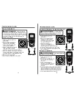
Page 28: ... se conecta a un voltaje fantasma Voltaje Low Z AC DC Siga todas las precauciones de seguridad cuando se trabaja con voltajes en vivo No conecte a circuitos que excedan 300V cuando el probador esté ajustado al modo de baja impedancia Low Z No utilice Low Z al probar circuitos que pudieran resultar perjudicados por la entrada de baja impedancia de esta función ADVERTENCIA n m VA FMk AUTO HOLD MAX M...

Page 29: ...ón de HZ 2 Pulse el botón de MODE para seleccionar la frecuencia o el del ciclo de trabajo El símbolo Hz o aparecerá en la pantalla LCD 3 Inserte el cable de prueba negro en la toma de entrada COM y el cable de prueba rojo en la toma de entrada V 4 Toque el circuito bajo prueba con las puntas de los cables de prueba 5 Lea la frecuencia o el del ciclo de trabajo en la pantalla LCD Mediciones de Fre...

Page 30: ...cable de prueba rojo en la toma de entrada Ω 4 Toque el dispositivo o cable bajo prueba con las puntas de los cables de prueba 5 Sonará un pitido si la resistencia es de aproximadamente 40Ω o menos y el valor de la resistencia se mostrará en la pantalla LCD Continuidad Nunca pruebe la continuidad en un circuito vivo ADVERTENCIA n m VA FMk AUTO HOLD MAX MIN REL LOZ 0 10 20 30 40 n m VA FMk AUTO HOL...
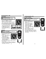
Page 31: ...robador hasta que la cubierta de la batería fusible esté bien conectado al probador ADVERTENCIA Para evitar descargas eléctricas retire los cables de prueba del medidor antes de retirar la cubierta de la batería fusible ADVERTENCIA n m VA FMk AUTO HOLD MAX MIN REL LOZ 0 10 20 30 40 15 Operación cont Mediciones de Temperatura 1 Coloque el interruptor de función rotativa en la posición de F C 2 Puls...
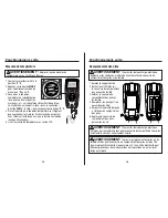
Page 32: ...dor Los tornillos sueltos o muy ajustados o una junta tórica asentada incorrectamente pueden poner en peligro la protección contra la entrada del agua y el polvo en el probador ADVERTENCIA 18 Especificaciones 4 000V 40 00V 400 0V 600V Todos los rangos de voltaje AC se especifican de 5 a 100 del rango Protección de Entrada 600V AC RMS o 600V DC Impedancia de Entrada 7 8MΩ Respuesta AC 50 a 60Hz 1mV...

Page 33: ...rriente DC Función Rango Resolución Precisión de lectura dígitos 20 Especificaciones cont 40 00nF 400 0nF 4 000µF 40 00µF 400 0µF 4000µF Protección de Entrada 600V AC RMS o 600V DC 10pF 100pF 0 001µF 0 01µF 0 1µF 1µF 5 0 50 dígitos 3 0 5 dígitos 5 0 10 dígitos Capacidad Función Rango Resolución Precisión de lectura dígitos 9 999Hz 99 99Hz 999 9Hz 9 999kHz 99 99kHz 999 9kHz 9 999kHz Protección de E...

Page 34: ... INCUMPLIMIENTO DE ESTA GARANTÍA Esta garantía no será válida si el producto se utiliza para propósitos de alquiler Ningún vendedor de productos está autorizado a extender la garantía a nombre de Southwire en relación a este producto y la garantía de ningún vendedor será vinculante para Southwire Si necesita reclamar una garantía o si el producto necesita servicio durante o después del periodo de ...

Reviews: