Installation Procedure continued
9. If using Southwire switch assembly MH2021, mount switch face plate in desired location using appropriate hardware. If using South-
wire switch assembly RV2100, follow instructions included with switch. If using alternate switch not supplied by Southwire, mount
switch according to manufacturer’s instructions. It may be necessary to mount switch after wiring to help with the routing and termi-
nation of wires. Be sure to mount and secure all wires to prevent any possible mechanical damage to outer insulation on the wires.
WARNING: To reduce the risk of electric shock, disconnect the 12VDC power source prior to proceeding.
10. Find the nearest 12 VDC power source. The power source must be from a circuit protected by a 20 Amp circuit breaker. Using power
from a compartment is not recommended as these normally do not have a high enough amperage rating.
11. Route the wiring to the desired position of the switch previously located.
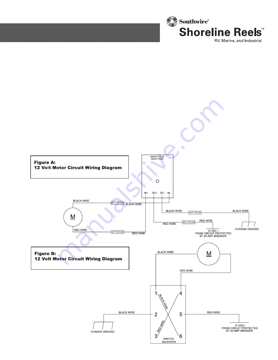
12. If using Southwire switch assembly RV2100, follow instructions included with switch. If using Southwire supplied switch assembly
MH2021, refer to wiring diagram (Figure A). If using an alternate switch not supplied by Southwire refer to wiring diagram (Figure B).
Alternate switch must be a DPDT, (ON) OFF (ON) rocker type capable of handling 20 Amps VDC. All wiring regardless of switch used
must be 14 AWG with all applicable terminals sized appropriately.
13. Reconnect the 12 VDC power supply.
14. Test the unit by following steps listed in OPERATING INSTRUCTIONS
MODEL #RL5
IMPORTANT SAFETY
INSTRUCTIONS
505-00094B


