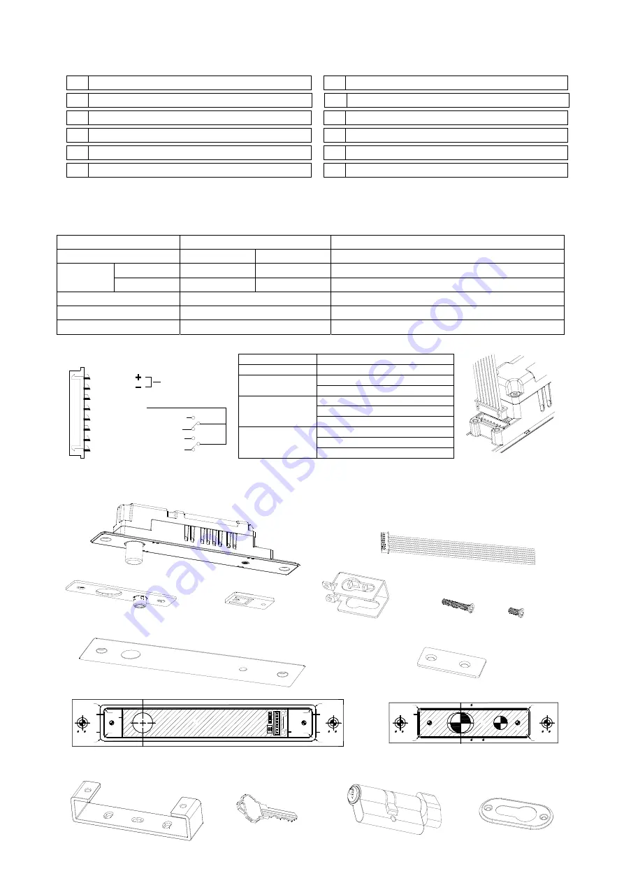
AR-1203P Installation Manual
SOYAL
Technology Co., Ltd.
www.soyal.com
I.
Order Information
∨ 1. Whole alloy housing
∨
7. Auto-detective logical
∨ 2. Dual Voltage: 12V / 24VDC(By 4-pin jumper)
∨
8. Lock status sensor output (LSS)
∨ 3.Timer Setting: 0, 3, 6, 9 sec. for door locking
∨
9. Door position status output (DSS)
∨ 4. Bicolor indicators: Dual LED
×
10. Warning buzzer
∨ 5. Exit Switch Input: No, momentary contact
×
11. Connect Bicolor
∨ 6. Latch off mode: press exit switch will hold
×
12. With Mortice Lock Cylinder
Note:a.
Latch off mode
(If connected with latch type of exit switch, the bolt lock will be as N.O. without
activated till switch off.)
b. Connect Bicolor (Capability to extend the bicolor indicator by external indicators about 50cm)
II.
Specifications
Item
Contents
Remarks
Power Input and Tolerance
12VDC
24VDC
Stable PSU recommended
Pull in
1.20A
0.68A
Changeable by power input and higher outer temp.
Current
Draw
Holding
0.22A
0.16A
Changeable by power input and higher outer temp.
Surface Temperature
< 40 ℃
Room Temp. 25 ℃
DSS
Max.3W; Max.30VDC;Max.0.2A COM,NO,NC
LSS
Max.30VDC;Max1A
COM,NO,NC
III.
Wiring diagram
Red
: V
Black
: V
Gray
: No
Green
: No
Browm
: Nc
Power input
White
: Nc
Blue
: COM
Max
Door Closed
1.0A
Max
0.2A
(
)
Door Open
(
)
Bolt unlock
(
)
Bolt locked
(
)
Yellow
:
Exit switch
V+ (+12/+24VDC)
Exit Switch
V- (GND)
DSS
(Door Status Sensor)
LSS
(Lock Status Sensor)
Red (22AWG)
Black (22AWG)
One close to Black
(22AWG)
One close to Yellow (26AWG)
COM-Blue (26AWG)
NO-Gray (26AWG) Door Closed
NC-White (26AWG) Door Open
COM-Blue (26AWG)
NO-Green (26AWG) Bolt unlock
NC-Brown (26AWG) Bolt locked
WIRING DIAGRAM
※ Caution:Please make sure the “+” and “-” wires are connected well and correctly before you apply a power source to
the lock; Warning, Reverse polarity will make a short circuit and void products warranty.
IV.
Contents
D e c o r a t i v e P l a t e x 1
L o c k b o d y x 1
W i r e h a r n e s s x
1
S t r i k e r p l a t e x 1
M T G . T A B x 4
M 5 - 8 L x 8
M L C - U - B r a c k e t x 1
M 5 - 3 0 L x 1
W D - F a c e P l a t e x 1
R4
R4
R3
R3
CTSK
6
×
10
A
C
R4
R4
R3
R3
A
C
CTSK
M5
A : 195
×
27.4 mm B : 155
×
27.4 mm C :202
×
34 mm
B
B
6
×
10
M5
R3
R3
R3
R3
A
C
D
A : 105
×
27.4 mm
C : 19 - DEEP 20 mm
B : 102.55
×
25.4 mm
B
6
×
10
M5
M5
6
×
10
CTSK
CTSK
D
D : 12 or 13 - DEEP 12 mm
T e m p l a t e - L x 1
T e m p l a t e - S x 1
V.
Assembly materials (From Order)
MLC-Key
MLC-Cover
Mortice Lock Cylinder
WD-U-BRACKET
- 1 -


