background image

2

 Hardware Setup

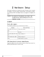
This chapter explains how to configure the mainboard's hardware. After you install

the mainboard,  you can set jumpers, install memory on the mainboard,  and make
case connections. Refer to this chapter whenever you upgrade or reconfigure your
system.

CAUTION:  Turn off power to the 

mainboard, system 

chassis, and

peripheral devices before performing any work on the

mainboard  or system

Jumpers

Factory Set Jumpers

'

The following jumpers are set at the factory as below. -

Jumpers Factory settings

JP28, JP29, JP31,  JP36, JP37, Factory fixed at Short

JP47

J21

Reserved

JP5, JP34, JP48, JP53,  JP50, Factory setting at 1-2
JP51

JP28,  JP29,  JP32,  JP33, JP47 Factory setting at 2-3

JP30

Factory freed at 3-5 and 4-6

JP25:

 Sleep Switch Connector Enable/Disable

Toggle this jumper to force the system into power saving (Green) mode. Any
hardware IRQ signal makes the system wakeups.

Summary of Contents for 5SM2

Page 1: ...j p l Pentium...

Page 2: ...t described within it at any time without notice and without obligation to notify any person of such revision or change The information contained in this manual is provided for general use by our cust...

Page 3: ...ack Write Through Cache Select 8 JP46 VRM Voltage Regulator Module Socket Optional 8 JPS2 PS 2Mouse FunctionJumper 8 JP38 JP42 Bus Fraction Core Bus Ratio Select 9 JP40 CPU Burst Mode Select 10 CPU Ty...

Page 4: ...oAdapterFunction 19 WTC1 Wave Table Card Connector 19 SB1 Audio Adapter Connector 19 J1 CD ROMAudio In Connector 19 JACK1 Speaker Out Jack 19 JACK2 Line OutJack 19 JACK3 LineInJack 19 JACK4 MCInJack 1...

Page 5: ...r Concurrent Write Back CAS before RAS Transparent DRAM Refresh 256K 512K lM 2M 4M or 16M x N 70ns Fast Page and EDO DRAM symmetric and asymmetric On board memory configurations from 2 to 512 Mbytes S...

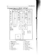
Page 6: ...pset Pipelined Burst SKAM Module Slot PnP FLASH BIOS Audio Chipset ISA Slots PCI Slots SIMM Memory Bank 5V DC Power Connector Keyboard Connector 13 14 15 16 17 18 19 20 21 U PS 2 Mouse Connector IDE1...

Page 7: ...bled PIO Mode FDD Enabled 2 high speed UART Enabled w 16550 FIFO 1 EPP ECP port standard mode and PS 2 Mouse Disabled 1 111111 1111 2 I ISA SLOT LPrmii JP48 I I D u PCI SLOT 65 m m N Wave Table Connec...

Page 8: ...256 colors NI or 1280x 102464K colors Interlace only Supports virtual screen up to2048 x 2048 Supports sofiware MPEG function Resolutions Supported Resolution 1 MByte DRAM 2 MByte DRAM 640x480x256 I I...

Page 9: ...d contact your dealer immediately Electrostatic Discharge Precautions Make sure you ground yourself before handling the mainboard or other system components Electrostatic discharge can easily darnage...

Page 10: ...l devices before performing any work on the mainboard or system Jumpers Factory Set Jumpers The following jumpers are set at the factory as below Jumpers Factory settings JP28 JP29 JP31 JP36 JP37 Fact...

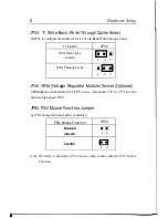
Page 11: ...rough Cache m 1 2 3 JP46 VRM Voltage Regulator Module Socket Optional VRMsocket is dedicated for 2 5V CPU to use It converts 3 3V to 2 5V for the advance high speed P54CX JPS2 PS 2 Mouse Function Jump...

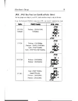
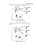
Page 12: ...e Setup 9 JP38 JP42 Bus Fraction Core Bus Ratio Select Set this jumper according to your CPU clock and this setting is only for Pentium Note For PentiumX YMHz X stands for CPU core clock Ystandsfor bu...

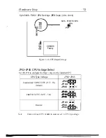
Page 13: ...ault Linear burst for Cyrix CPU Type Configuration JP40 3 2 1 Set the mainboard ss CPU jumpers JP23 and JP24 according to CPU type as described below and then set JP43 JP45 for the proper voltage of t...

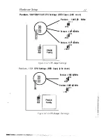
Page 14: ...Pentium 100 50 MHz JP23 P23 El JP24 Pentium 120 60 MHz JP23 HI p m2 Pentium 133 66 MHz JP23 El o JP240 Figure 2 1 2 CPUJumper Settings Pentium 150 CPU Settings RED Caps 2 5x clock Pentium 150 60 MHz d...

Page 15: ...MHz JP23 III J P 2 4 Pentium 200 66 MHz JP23 El o JP24 Figure 2 1 4 CPUJumperSettings Cyrix 6x66 P120 P150 P166 CPU Settings RED Caps 2 0x clock 6x66 P120 50 MHz JP23 EEl JP24 6x66 P150 60 MHz J 3 z J...

Page 16: ...Settings JP43 JP45 CPU Voltage Select Set JP43 JP45 to configure the Proper voltage for the installed CPU CPU Type Voltage JP43 JP45 Standard and VR P54CX CPU 33V 5 5 JP43 Default JP44 JP45 1 H JP43 V...

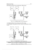
Page 17: ...emory configuration is thus Table Free You can use single 32 bits DRAM on SIMM2 and SIMM4 Cache Configuration The mainboard has a write back caching scheme You can configure the mainboard s s cache by...

Page 18: ...Pipelined Burst Cache Configuration 512K Pipelined Burst Cache Configuration White Caps A 256KB Pipelined Burst upgrade module has to install into Pipelined Burst Module Slot J23 Figure 2 3 512K Pipel...

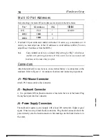
Page 19: ...use sound card functions at the same time you print Connectors Attach the mainboard to case devices or an external battery via connectors on the mainboard Refer to Figure 1 1 for connector locations...

Page 20: ...19 Closing the Reset switch restarts the system J20 External Battery Connector J20 is a 4 pin connector to which you can attach an external battery Pin 1 of J20 is positive and pin 4 is negative J22 T...

Page 21: ...Connector Attach parallel port cable to this connector VGA Connector Optional Attach VGA cable to this connector VGA Feature Connector Optional Attach VGA Feature cable to this connector AUDIO Connect...

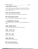
Page 22: ...apter Connector Attach this end to the audio connector of the motherboard for connection JI CD ROM Audio In Connector Attach CD ROM Audio line to this connector for transferring CD ROM s audio to the...

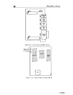
Page 23: ...20 Hardware Setup 1 I Figure 2 4 1 Top Viewof the Audio Adapter Attach Audio Adapter here 1 HnISA u n H SLOT u I El Figure 2 4 2 Audio Adapter Connection...

Page 24: ...URES SETUP POWER MANAGEMENT SETUP PCI ONBOARD 1 0 SETUP LOAD SETUP DEFAULTS Esc Quit F1O Save Exit SetuD IDE HDD AUTO DETECTION SAVE EXIT SETUP EXIT WITHOUT SAVING Select Item Shift F2 Change Color Ti...

Page 25: ...deo EGA VGA Halt On All Errors Total Memory 4096K Esc Quit r4 Select Item PU PD Modify F11 Help shift F2 Change Color F3 Toggle Calendar 2 Use arrow keys to move between items and select values Modify...

Page 26: ...00 DBFFF Shadow Disabled Gate A20 Option Fast DCOOO DFFFF Shadow Disabled Memory Parity Check Disabled Typematic Rate Setting Disabled Typematic Rate Chars See 6 Typematic Delay Msec 250 Security Opti...

Page 27: ...drive A and then from hard disk C You can reverse this sequence with C A but then drive A cannot boot directly Enabled changes the sequence of the A and B drives The Default setting is Disabled Choos...

Page 28: ...r ROM to faster RAM BIOS can then execute from RAM These 16K segments can be shadowed from ROM to RAM BIOS is shadowed in a 16K segment if it is enabled and it has BIOS present 3 After you have finish...

Page 29: ...tup Defaults 2 Use the arrow keys to move between items and select values Modify selected fields using the PgUp PgDn keys A short description of screen iterns follows Auto Configuration Enable this op...

Page 30: ...OOH C7FFFH is cacheable if cache controller is enabled Choose Enabled or Disabled default Some interface cards will map their ROM address to this area If this occurs you should select Enabled otherwis...

Page 31: ...5 Activity Enabled F1 Help PU PD Modify F5 Old Values Shift F2 Color I F6 Load BIOS Defaults F7 Load Setup Defaults 2 Use the arrow keys to move between items and to select values Modify the selected...

Page 32: ...de Time is adjustable from 20 seconds to 40 minutes Under Suspend mode the CPU stops completely no instructions are executed The hardware monitors these ports for activity If activity occurs from the...

Page 33: ...lave PIO Auto F6 Load BIOS Defaults IDE HDD Block Mode Enabled F7 7 Load Setup Defaults These items will disappear when PnP BIOS Auto Config is enabled 2 Use the arrow keys to move between items and s...

Page 34: ...ault Disabled INTC or INTD The INTC or INTD The Primary Secondary or Both Turns on the Primary and Secondary IDE function Primary Turns on the Primary IDE function Secondary Turns on the Secondary IDE...

Page 35: ...t is connected to the port Choose 3 default or 1 This option is available only when ECP mode and Parallel port 378H 278H are selected Choose Enabled or Disabled to enable or disable the MIDI function...

Page 36: ...rm the new password Confirm Password Re enter your password and then Press ESC to exit to the Main Menu Important If you forget or lose the password the only way to access the system is to set jumper...

Page 37: ...m is to set jumper JP5 to clear the CMOS RAM All setup information is lost and you must run the BIOS setup program again IDE HDD Auto Detection This Main Menu item automatically detects the hard disk...

Reviews: