Introduction
SY-5EMM
29
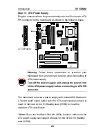
ATX Power
12V
5VSB
PW-0K
GND
5V
GND
5V
GND
3.3V
3.3V
5V
5V
-5V
GND
GND
GND
PS-ON
GND
-12V
3.3V
Please install the ATX power according to the following pin
assignment:
Ø
Pay special care to the directionality.
Step 14. CMOS Clearing (JP5)
After you have turned off your computer, clear the CMOS memory
by momentarily shorting pins 2-3 on jumper JP5, for a few seconds.
Then restore JP5 to the initial 1-2 jumper setting in order to recover
and retain the default settings.
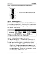
CMOS Clearing
Clear CMOS Data
Retain CMOS Data
JP5 Setting
Short pin 2-3 for
a few seconds to
clear the CMOS
Short pin 1-2
to retain new
settings
Note: You must unplug the ATX power cable from the ATX power
connector when performing the CMOS Clear operation.
Step 15. Onboard Sound Jumpers (JP19,JP20)
The onboard audio features of your mainboard are controlled by
jumpers JP19 and JP20. You can choose to enable or disable the
available sound function by setting JP19 and JP20 accordingly.
l
Open pins on jumpers JP19 and JP20 to enable the onboard sound
function. Then, you can plug your external audio devices such as
amplified-speakers, CD-player, and microphone to the mainboard
Line-out, Line-in and Mic ports right after the mainboard is installed.
(You do not need to install any sound card.)
3
2
1
3
2
1

