Motherboard Description
SY-P4I875P DRAGON 2
9
H
Chassis Cooling Fan (CHAFAN2) connectors
This connector is to connect your chassis fan to your motherboard.
This motherboard supports up to 3 chassis fans. Please check the
(2)
Chassis Cooling Fan (CHAFAN1, CHAFAN2, CHAFAN3)
paragraph on page 34 for more details.
I
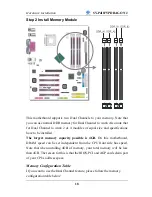
DDR DIMM Banks
These 4, 184 pin memory slots are to install your system memory in.
They support up to 4 GB of memory. For more details check the Step
2 Install Memory Module
paragraph on page 18.
J
ITE IT8712F-A Super I/O Chip
The IT8712F-A is a Low Pin Count Interface-based highly
integrated Super I/O. The IT8712F-A provides the most commonly
used legacy Super I/O functionality plus the latest Environment
Control initiatives, such as H/W Monitor, Fan Speed Controller,
ITE's 'SmartGuardian' function and Smart Card Reader Interface.
The device's LPC interface complies with Intel 'LPC Interface
Specification Rev. 1.0'. The IT8712F-A meets the 'Microsoft® PC98
& PC99 System Design Guide' requirements, and is ACPI &
LANDesk compliant.
K
Serial Infrared (IrDA) device header
This header allows you to connect an IrDA receiver to the
motherboard. You can find the lay-out in the
1. Standard Infrared
(SIRCON)
paragraph on page 32.
L
Smart Card Reader connector
This connector allows you to connect a smart card reader to the
PC/SC, ISO 7816 compliant onboard smart card reader. The
paragraph
3. Smart Card Reader
on page 35 contains more
information on the lay-out of this header.
M
ATX Power Supply connector
This connector is to connect the ATX connector of your ATX12V
compliant power supply to the motherboard. For more details on this
connector, please check the
F. ATX12V Power Supply
paragraph
on page 39.
N
Floppy Disk Drive (FDD) connector
This 34 pins connector is to connect your floppy drive to. Check for
more details in the
B. Floppy Drive Installation
paragraph on page
25.
Summary of Contents for SY-P4I875P DRAGON 2 V1.0
Page 12: ...Motherboard Description SY P4I875P DRAGON 2 7 1 7 SY P4I875P DRAGON 2 MOTHERBOARD COMPONENTS ...
Page 120: ...115 APPENDIX A HighPoint HPT 372 ...
Page 127: ...122 APPENDIX B Silicon Image 3112 ...
Page 130: ...125 APPENDIX C Flashing BIOS ROM ...
Page 132: ...127 5 Press ALT F2 to start up AWDFLASH You should see the following screen ...
Page 133: ...128 6 AWARD flash will now automatically flash your BIOS and reset when it is done ...
Page 134: ...129 APPENDIX D Troubleshooting ...


