background image

The 

Galaxy

 stair can be operated by use of the remote control (provided), a hard-wired wall switch 

(optional) or both. This guide will help you set up your unit for wall switch operation. 


The switch itself is purchased separately and is available at most hardware / 
home improvement stores or electrical supply houses. 


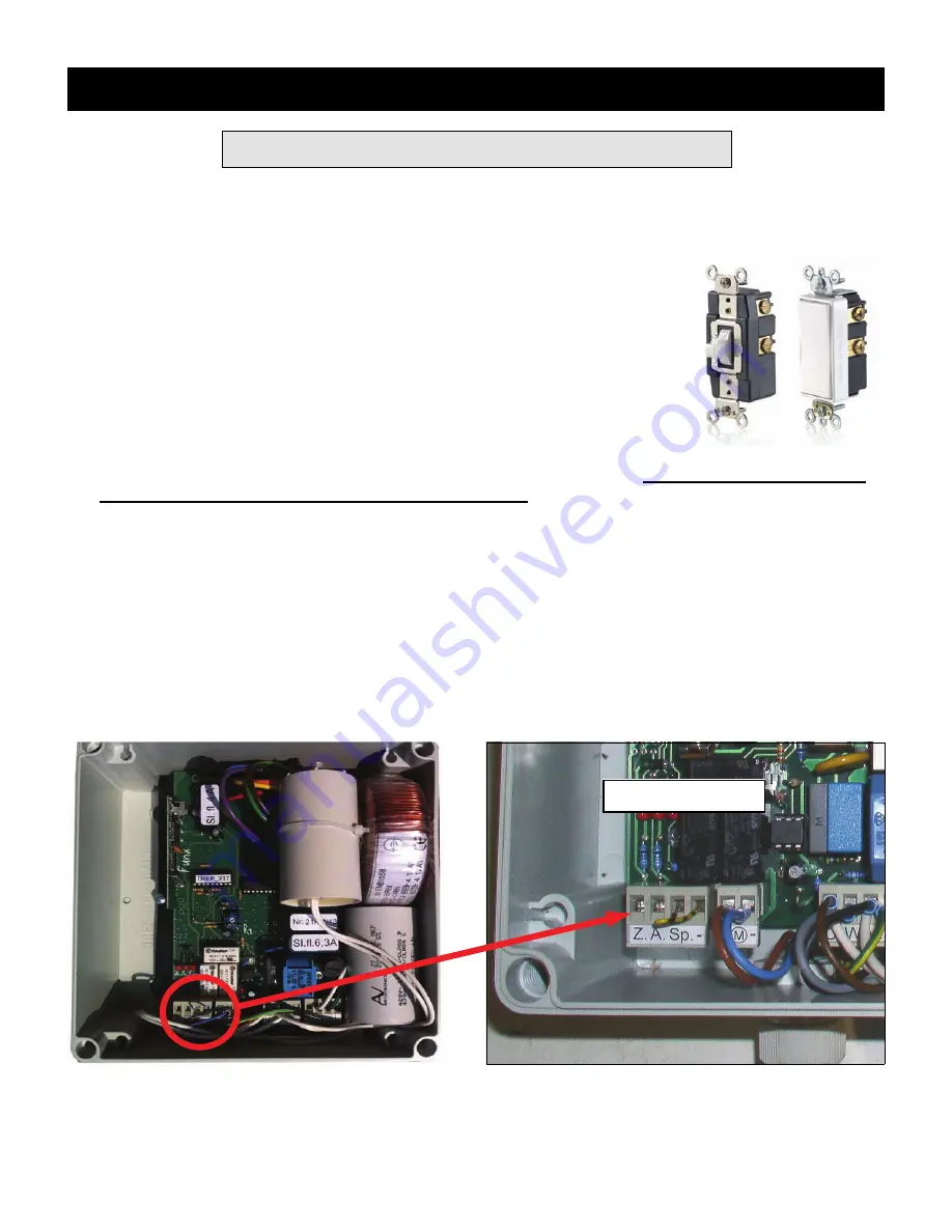
It should be a low voltage, momentary contact, center OFF type. One  offered  
by 

Leviton, (Product # 56081-2)

, is available in both toggle style and Decora 

style as shown at right and works well in this application. 


Step 1. 
 

Locate the position of the electrical box to house the switch on the wall. 

The switch should be set at 

a height which will prevent children from reaching it. 


Run three low voltage wires from electrical box to where stair control box is located in attic. It may be 
useful to use three different wire colors for easy identification. 


Step 2.


Unplug the control box in attic from the power outlet and remove cover. 


Remove wiring module from control box by grasping module and rocking slowly while pulling up to re-
lease it.  


Control Box 

Wiring Module 

Addendum - Continued 

Hard Wiring Instructions 

Page 12 

July 2014 

Summary of Contents for Rainbow Attic Stair Galaxy G2755

Page 1: ...www RainbowAtticStair com By SP Partners LLC INSTALLATION GUIDE Galaxy ...

Page 2: ...ds that should be installed for your height refer to Table A on page 3 Do not add or remove treads solely for changing the angle of the stair This will cause an unsafe condition and damage the stair Adjustment Screw on stabilizer arm MUST be set before climbing stair This adjustment provides structural support necessary for use See page 7 Failure to follow any or all of these guidelines can result...

Page 3: ...mber with same dimensions as joists keyhole saw or utility knife to cut ceiling material Page 2 July 2014 Parts Included Tools Materials Required 4 3 8 Threaded Rod 4 Joist Hanger 8 3 8 Hex Nut 10 3 Lag Screw 1 Door Hook 1 Wood Dowel 1 Door Opening Ring 3 Extra Steps Remote Control ...

Page 4: ...aming supports Improper installation can result in stair collapse and bodily injury Determine location of electrical lines or plumbing before cutting ceiling WARNING Page 3 July 2014 Table A MODEL COLOR ROUGH OPENING SIZE FRAME DIMENSIONS TREAD WIDTH FLOOR TO CEILING HEIGHT RANGE NUMBER OF STEPS PROJECTION LANDING SPACE G2755 as assembled GRAY 27 3 4 X 55 1 4 27 1 4 X 54 3 4 14 7 2 to 7 10 9 6 51 ...

Page 5: ... parallel to the ceiling joists Figure 3 In cases where they are installed perpendicular to joists Figure 4 some joists will need to be cut and tied in to other joists with headers of the same dimensions as the joists and will form the box frame into which the stair will be secured Before cutting any joists watch out for electrical wiring If your attic is constructed using trusses DO NOT CUT CEILI...

Page 6: ...angers are installed With hangers holding stair in place helpers can let go 4 Square stair to frame Try to maintain an even gap all around between stair and headers 5 Tighten nuts in stages all around Do not over tighten as this may distort metal trim on ceiling side 6 Attach door opening hook to wood dowel using 2 1 2 wood screws Figure 7 7 Door can now be opened but DO NOT EXTEND OR STAND ON STA...

Page 7: ...ure 10 Additional hardware is provided with extra treads 3 Re attach bottom tread Page 6 July 2014 There are two buttons on the remote The center button will lower the stair other button will raise it See Figure 8 You will see a red light at tip when pressed As a safety feature the remote control will send a signal to the stair unit and raise or lower the stair only while the buttons are depressed...

Page 8: ...om of stabilizer arm These screws will stabilize and sup port stair against door as you climb up and down Screws set too high will prevent stair from making contact with floor and create leverage that can cause damage to stair 5 Insert door opening ring into eyelet on face of door Figure 12 6 Press and hold remote button to raise stair Hold button until door is fully closed and the latch engages N...

Page 9: ... a power outage the stair can be operated manually The long pole with hook Figure 7 is supplied for this purpose To Open Stair 1 Insert hook provided into ring on door face and pull door down until fully open Figures 14 Door should stay in place at full open position 2 Grab bottom tread with hook and pull slightly away from door to start unfolding stair Figures 15 Never pull straight down as the s...

Page 10: ...tic Stair As with any product be sure to follow instructions for safe efficient and trouble free operation for years to come Children should never be allowed to operate or climb any attic stair Figure 14 Figure 15 Figure 16 Figure 17 Stabilizer Arm Page 9 July 2014 ...

Page 11: ...tton Step 1 Step 2 Step 3 Press black button A twice The other light comes on Press and hold button C until top light blinks rapidly and turns off Release but ton Remote is now programmed B C Addendum Programming A Second Remote A Press and hold black button A until top light blinks then goes out and bottom light turns on Release button Program is now cleared To reprogram repeat Steps 2 and 3 abov...

Page 12: ...n the control box They are spring loaded in a barrel housing To remove push down and turn counter clockwise to release Remove cap to check or re place fuse Re insert cap and push down while turning clockwise to lock Fuses Checking Replacing Fuse 1 4 amp Fuse 2 6 3 amp ...

Page 13: ... as shown at right and works well in this application Step 1 Locate the position of the electrical box to house the switch on the wall The switch should be set at a height which will prevent children from reaching it Run three low voltage wires from electrical box to where stair control box is located in attic It may be useful to use three different wire colors for easy identification Step 2 Unplu...

Page 14: ...osen the three screws on front of module for slots shown above Insert individual wires as shown and secure each by re tightening screws Do not remove existing wire already in slot marked Carefully press module back onto circuit board Note It is advisable to fill hole around wires with clear rubber sealant to prevent insects dirt or moisture from entering box Step 5 Plug the control box back into t...

Page 15: ...tch press the switch for both Up and Down Corresponding light should go on when pressed as shown below If all is working properly replace cover on control box Your unit is now ready for use If you encounter any problems contact Shelter Products LLC at 877 369 6996 Down Light Up Light Power Light Always On Page 14 July 2014 ...

Page 16: ...if closed Press remote to open and check if door latch retracts automatically Door opens but stair will not fully unfold starts and stops Is there a metal roof on the building Metal roofs create dead spots which can interfere with the remote s signal While closing door stops short of closing fully Does not go fully up into frame Check that bolts holding extra treads together at bottom of stair are...

Page 17: ...mplied warranties of any kind including those as provided by the Uniform Commercial Code for merchant ability of the product and for fitness of the product for a particular purpose All such implied warran ties including those of merchantability and or fitness for a particular purpose are excluded and disclaimed Furthermore all claims for consequential damages and for incidental damages that may ar...

Reviews: