___________________________________________________________________________________________
4
EG300
0
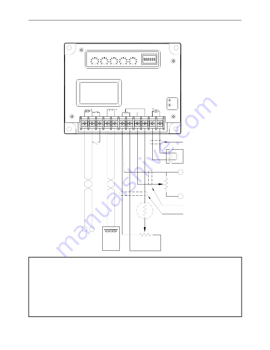
SECTION 5 : WIRING CONNECTIONS
DC Power
+
_
Cable A
Cable C
Magnetic
Pickup
Actuator
Idle
switch
CCW
VR1 5K
CW
Analogue
Input
Cable B
VR2
DROOP
DIF.
INT.
GAIN
RAMP
SW1-ON 600~1200HZ
SW2-ON 1200~2500HZ
SW4-ON 5000~9500HZ
SW3-ON 2500~5000HZ
POWER : DC12/24V
IDLE
1
2
3
ACT
4
5
6
7
MPU
9
ILS
8
10
11
~
+
REMOTE
SPEED POT
RUN SPEED
IDLE SPEED
SW5-ON PT-PUMP
EG300
0
+
SW6-ON Slow response
SW
R
3
1
2
1K
3
1
2
CCW
CW
ATTENTION
1. The unit must be installed by qualified technical personnel. Improper installation, wiring or settings could lead
to injury to personnel and/or damage to equipment.
2. This unit has no Over Speed Protection function. It is recommended to install a separate over speed
protection device.
3. The battery connects directly to the controller with a fuse for protection. Use 20A slow-blow fuse.
4. Terminals 1, 2, 4, 5 must use 2.0 mm2 (14 AWG ) or larger wires.
5. Cables A, B, and C must be copper shielded cable of 26 AWG or larger.
6. In order to reduce noise interference copper shielding should be grounded on one end only.


