background image

Optional Sample Extractor Assembly 

FTS Systems LyoStar™ II 


38 


Rev 012, 04/11 


© SP Scientific 2011 

SEA Installation Instructions 

Note: Field replacement of the standard door, with a SEA, requires two people. 


Standard Door Removal 


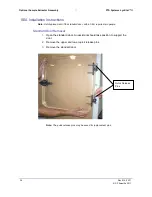
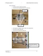
Open the standard door. An assistant should take position to support the 

1.

door. 


Remove the upper and lower quick release pins.  

2.


Remove the standard door. 

3.


Note: The quick-release pins may be saved for replacement pins. 

Quick Release 
Pins 

Summary of Contents for LYOSTAR II

Page 1: ...LYOPHILIZER OPERATOR S MANUAL FTS SYSTEMS LYOSTAR II STANDARD...

Page 2: ......

Page 3: ...ny means and in any form or manner is expressly prohibited except with the prior written permission of SP Scientific Permitted copies of this document must retain all proprietary notices contained in...

Page 4: ...at transfer vacuum and electrical systems Always ensure that refrigeration air intake is clear and clean Always ensure vacuum pump exhaust is properly ventilated and or contained Always practice team...

Page 5: ...Company employees Replacement or repair of parts pursuant to this warranty shall not in any way extend the original warranty period The Company shall not be responsible for any unauthorized repairs re...

Page 6: ...iv Rev 012 04 11 SP Scientific 2011...

Page 7: ...Units Only 6 Vacuum Pump Installation 6 Door Closure 7 Internal Stoppering Operation 7 Operating Your Lyophilizer 9 Leak Rate and Function Testing 9 Leak Rate Testing 12 System Testing 13 Thermocouple...

Page 8: ...37 Description 37 SEA Installation Instructions 37 Standard Door Removal 38 SEA Installation 39 Operation 40 Shelf Area 42 Electrical Requirements 42 Optional Isolation Valve 43 Isolation Valve 43 El...

Page 9: ...11 Chapter 1 Introduction Overview The LyoStar II research and development freeze dryer is comprised of 4 major components Tray chamber 1 Condenser chamber 2 Computer workstation 3 Vacuum pump accesse...

Page 10: ...he software package of this system is a Power Point presentation on system operation and the purpose of all of the software screens Double click the LyoManager icon on the desktop Click Lyobrary on th...

Page 11: ...nd related paperwork intact until a written report is obtained Note SP Scientific will cooperate in the matter of collecting your claim but is not responsible for the collection or free replacement of...

Page 12: ...f as needed automatically If the system is shut down and then quickly restarted it may take several minutes for the compressor to restart Placement and Initial Set Up Review the Layout Drawing from yo...

Page 13: ...es are necessary because of the lower temperature specification of these units Check the voltage requirements stated on your serial tag against your power supply Note These systems will not work prope...

Page 14: ...ot operate the LyoStar II with cooling water above 86 F 30 C The unit will add approximately 20 000 BTUs hour at steady state to your facility water Peak demand could be as high as 25 000 BTUs hour Va...

Page 15: ...pering less than a full tray of bottles to make sure that the stoppering switch is deactivated once the stoppers are seated in the bottles Stoppering less than 10 vials per shelf is not recommended Em...

Page 16: ...ermined so that full torque is available to stopper all sizes of containers This torque may cause bottle breakage or shelf warping if held in the UP position for too long When the stoppering switch is...

Page 17: ...lled and operational a leak rate and system test should be performed see page 12 13 for instructions on how to perform The baseline performance data should be kept with this instruction manual These s...

Page 18: ...he vacuum pump should evacuate the system from atmospheric to 100 mT in less than 20 minutes The System Test takes approximately 2 hours to run using the factory suggested parameters From the Main Men...

Page 19: ...11 From the Automatic Mode Select screen the operator can access Freeze Drying Screen to input recipe for automatic freeze drying process Defrost Defrost the condenser coil System Test Tests the integ...

Page 20: ...een will now be displayed 7 Enter values to test the performance of the unit The values SP Scientific uses 8 during QC testing are shown here Values may be altered but should be run consistently there...

Page 21: ...onsistently thereafter to accurately compare performance from run to run If desired customize the system test data headings at this time by clicking on 4 the System Test Run Number and Operator fields...

Page 22: ...he sample with the thermocouple should be placed in the center of the product tray SP Scientific also offers a variety of Special Product Sensors which fit serum bottles with either a 13 mm or 20 mm n...

Page 23: ...ot homogenous and or the depth of product fill from tray to tray is irregular This mode allows the operator to manually control the freeze drying cycle without forfeiting the benefits of the safety fe...

Page 24: ...ve reached the setpoint subsequent cooling of the shelf and condenser will be slower than otherwise Once the condenser has reached a temperature of 40 C or lower click on 7 the Vacuum The vacuum pump...

Page 25: ...r assistance on any part of the software operation To print out data or import data to a spreadsheet please see the Data 12 Management Export to Spreadsheet section Note Isolate closes the butterfly t...

Page 26: ...a particular product The controller cools the shelves activates the condenser and vacuum pump and executes the operator selected program Basic Operation From the Main Menu screen select the Automatic...

Page 27: ...p to 0 C and hold for zero minutes Also program in some amount of time in the Extra Freeze Time field This is the part of the program to which the system will return if any overload or power outage co...

Page 28: ...ed the alphanumeric data headings while you were in the recipe screen the headings that will print with the data will be from the previous run If at any time during the run you require help programmin...

Page 29: ...FTS Systems LyoStar II Operating Your Lyophilizer Rev 012 04 11 21 SP Scientific 2011...

Page 30: ...nt step change the hold time to however much longer you want to hold Examples You are in Step 1 below and the system has been holding for 10 minutes You decide you want to hold for only 5 minutes more...

Page 31: ...This phase may not appear on the alphanumeric display If the shelf freeze setpoint is equal to the temperature programmed into the last programmed step of the freezing cycle Phase 2 is skipped Extra...

Page 32: ...eeze Dry Manual System Tests and Leak Rate runs are grouped under those headings and then by date If you open a file in Excel clicking through the wizard automatically dumps the data into Excel format...

Page 33: ...d Historical Screen The historical screen is an interactive trend that allows the user to view graphically how the run is progressing This entire graphing package is time based not batch based What th...

Page 34: ...ull the data accordingly Use the arrows on the bottom of the screen to scroll back and forth The graphical information will be displayed This graphing package also allows the user the ability to zoom...

Page 35: ...display Click and drag over a select area and release to enlarge To return to 100 click on Reset Zoom To change the axial scale double click the chart and fill information in the x y 3 axis fields Ea...

Page 36: ...Data Management FTS Systems LyoStar II 28 Rev 012 04 11 SP Scientific 2011 To print a graph click on a time under duration or specify the date 6 Click the print button at the top of the graph 7...

Page 37: ...melted 3 condensate into a container for disposal If your condensate includes corrosive solvents you may want to leave the 4 drain open during the entire defrost cycle This should allow the solvent to...

Page 38: ...Data Management FTS Systems LyoStar II 30 Rev 012 04 11 SP Scientific 2011...

Page 39: ...arly in the drying cycle During this time the trap can be valved so that it is on line The trap can be valved off line when the high vapor pressure solvents are gone This is indicated by a decrease in...

Page 40: ...LING LIQUIFIED GASES SHOULD BE THOROUGHLY INSTRUCTED AS TO THE NATURE OF THE MATERIAL LIQUIFIED GASES BECAUSE OF THEIR EXTREMELY LOW TEMPERATURE 129 C OR 200 F WILL BURN THE SKIN LIKE HOT LIQUIDS PROT...

Page 41: ...s it will go Note If sensor is not fully inserted liquid nitrogen will overflow out of the vent Note The vent line should not be obstructed in any way to avoid pressure build up Open the supply valve...

Page 42: ...oStar II 34 Rev 012 04 11 SP Scientific 2011 To by pass simply open the by pass valve and close the inlet and outlet 7 valves When liquid nitrogen is no longer needed shut off the supply line then 8 d...

Page 43: ...ragile Use care when raising and lowering the level sensor Loosen the black thumb screws and raise the lid up the shaft Do not lift the 4 lid off the top of the shaft Retighten the thumb screws to hol...

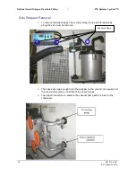
Page 44: ...move the side wrapper two screws along the top and three screws 1 along the side must be removed The hoses are long enough to set the wrapper on the ground Use caution not 2 to put excessive tension o...

Page 45: ...periodic removal of stoppered product containers for sample analysis The SEA is a pivotal option when the operator s mission is product development or stability studies Description The SEA is mounted...

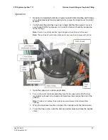
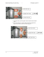
Page 46: ...Field replacement of the standard door with a SEA requires two people Standard Door Removal Open the standard door An assistant should take position to support the 1 door Remove the upper and lower q...

Page 47: ...remove both thumb screws 1 Remove the front antechamber plate with selector arm 2 3 With help from an assistant align the SEA in the hinge brackets 4 Re install the quick release pins 5 Re install th...

Page 48: ...techamber isolation door With locking handle in the up or 3 unlocked position the antechamber door can be slid open When antechamber isolation door is fully open lower the handle to lock the 4 isolati...

Page 49: ...pplied to the 8 vacuum break valve Remove the shroud from the stoppering ram to manually stopper the vial s 9 Open the inert gas fill vacuum break valve until the antechamber is back to 10 atmospheric...

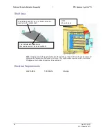
Page 50: ...l can be used and increases the accessible shelf area to 240 sq in This configuration requires vials to be rotated 90 degrees to a horizontal position to be removed Electrical Requirements LS FD SEA 1...

Page 51: ...essfully stepping into the drying portion of the program Use with Liquid Nitrogen Trap The auto filling liquid nitrogen trap is sold as an option The auto filling liquid nitrogen trap LNT LYOII is con...

Page 52: ...Optional Isolation Valve FTS Systems LyoStar II 44 Rev 012 04 11 SP Scientific 2011...

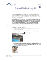
Page 53: ...latching kit to lock one or two of the shelves in the upright position Locking a single shelf would allow for two equally spaced shelves with a greater distance between shelves requires an LSLP 3 1 i...

Page 54: ...ing Kit FTS Systems LyoStar II 46 Rev 012 04 11 SP Scientific 2011 Secure wing nuts 4 Using the stoppering switch return the two available shelves to their full down 5 position The shelves are then av...

Page 55: ...iations from the standard LyoStar II configuration and can be applied to any software package in the LyoStar II family The LyoStar II research and development freeze dryer cleanroom configuration is c...

Page 56: ...s LyoStar II 48 Rev 012 04 11 SP Scientific 2011 Major Cleanroom Components Shelves Electrical Box Hour Meter and Fuse Panel System UPS Hydraulic Pressure Gauge Vacuum Pump Condenser Chamber Condenser...

Page 57: ...s properly located the leveling feet can be lowered to stabilize and level the unit Typically the shelves in the product chamber are used as the reference for adjusting the leveling feet Please note t...

Page 58: ...Optional Cleanroom Configuration FTS Systems LyoStar II 50 Rev 012 04 11 SP Scientific 2011...

Page 59: ...mum of four times a year Because system use and application varies from one facility to another system maintenance may need to be performed more frequently Synoptic Screen The Synoptic screen provides...

Page 60: ...and off individual components during routine servicing of the equipment It also provides you with information on the basic components Because system tune parameters and thermocouple calibration can be...

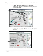
Page 61: ...fic 2011 To do this click on the component that you would like to activate 2 Example In this case we want to turn on the shelf fluid pump so we will click on the fluid pump image A screen will pop up...

Page 62: ...o the pump changes to ON 4 When you are ready to turn off the fluid pump click the OFF button to return 5 the pump back to its normal state Tune The Tuning screen is used to finely adjust the control...

Page 63: ...illivolt source at the thermocouple plug Click on the Auto calibration box To calibrate the machine place in ice bath millivolt source and press the Auto calibration button The system will zero itself...

Page 64: ...kly Check quality of the vacuum pump oil Visually Normally light and transparent change is required when discolorations increase For other testing methods refer to vacuum pump manual Check Shelf fluid...

Page 65: ...compressed air When using compressed air clean from the inside out Accumulation of dust in the condenser significantly reduces the amount of air passing through to cool the refrigerant Vacuum Cleanlin...

Page 66: ...General Maintenance FTS Systems LyoStar II 58 Rev 012 04 11 SP Scientific 2011...

Page 67: ...refrigeration system is not meant to be activated and deactivated in a short period of time If the system was just deactivated and the chugging noise occurred upon reactivation you may choose to turn...

Page 68: ...o have difficulties with the system after following these instructions contact the Service Department If the LyoStar II has a capacitance manometer controlling the pressure and the system is having di...

Page 69: ...n the condenser is 20 mT or below the vacuum troubleshooting has indicated that the vacuum leak is in the product chamber and you should proceed to step 5 If adequate vacuum is not achieved proceed wi...

Page 70: ...Appendix A Troubleshooting FTS Systems LyoStar II 62 Rev 012 04 11 SP Scientific 2011...

Page 71: ......

Page 72: ...SP Scientific 815 State Route 208 Gardiner NY 12525 USA 3538 Main Street Stone Ridge NY 12484 USA www SPScientific com 800 431 8232 845 255 5000...

Reviews: