background image

Form 44201360 


Oct 2019 

with  stacked materials,  sprinkler heads, gas and electrical lines, and any other possible obstructions or hazards.  
Consideration also must be given to service accessibility. 
 
Space-Ray will not recognize the warranty for any use other than space heating.  
This heater is for Indoor and Outdoor Installation and is used in Unvented mode. The term Unvented actually means 
Indirect Vented.  While the products of combustion are expelled into the building, codes require that ventilation by 
gravity  or  mechanical  means  shall  be  provided  to  supply  at  least  10m

3

/h  of  exhaust  air  per  kW  operating  heat 

input to dilute these products of combustion. 
 
This  heater  is  not  an  explosion  proof  heater.    Where  the  possibility  of  exposure  to  volatile  and  low  flash  point 
materials  exists, it could result  in  property damage or death.   This heater must not be installed in  a  spray booth 
where the heater can operate during the spraying process.  Consult your local fire marshal or insurance company. 
 
This heater must be applied and operated under the general concepts of reasonable use and installed using best 
building practices. 
 
It  is  the  responsibility  of  the  qualified  installer  to  supply  the  appropriate  lifting  equipment  to  safely  install  the 
radiant heater. Tools required for the safe installation, startup and maintenance are various screwdrivers, wrenches, 
pipe  wrenches,  voltmeter,  air  and  gas  manometer,  level  and  required  tools  to  safely  install  the  chosen  hanging 
materials. 
 

 Do not install this heater indoors in a structure with no insulation in the roof—condensation will 

occur. 
 
Before installation, check that the local distribution conditions, nature of gas and pressure, and adjustment of the 
appliance are compatible. 
 
These instructions refer to appliances designed to  operate in  the European  Union.  Appliances designed for other 
countries (Non-European Union) are available on request. 
 

This appliance can be used by children aged from 8 years and above and persons with reduced 
physical, sensory or mental capabilities or lack of experience and knowledge if they have been 
given supervision or instruction concerning use of the appliance in a safe way and understand 
the hazards involved. Children shall not play with the appliance. Cleaning and user maintenance 
shall not be made by children without supervision. 
 
Children must be supervised not to play with the appliance. 


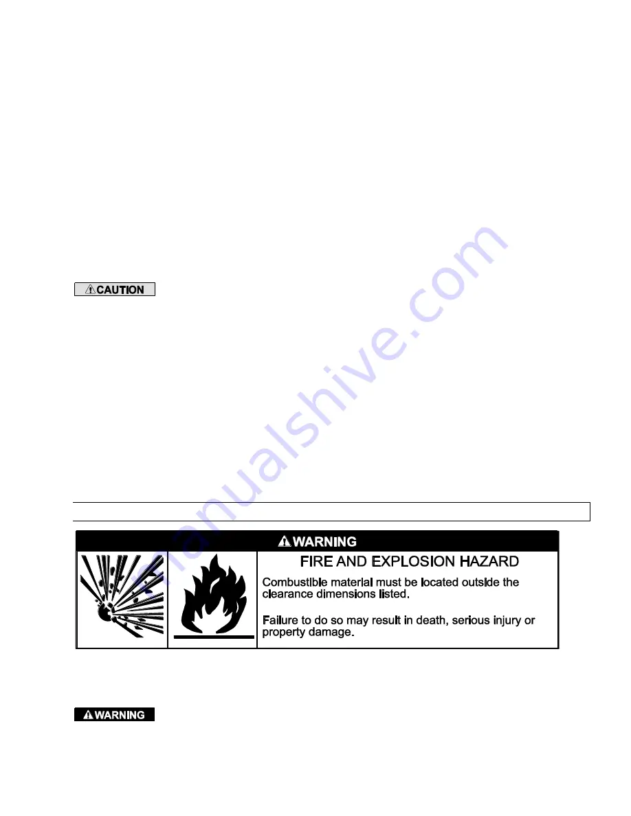
MINIMUM CLEARANCES TO COMBUSTIBLES 

4.0)


A  critical  safety  factor  to  consider  before  installation  is  the  clearances  to  combustible  materials.  Clearance  to 
combustibles  is  defined  as  the  minimum  distance  you  must  have  between  the  surfaces  of  the  heater  and  the 
combustible item. Considerations must also be made for moving objects around the infrared heater.  
 

 This heater must not be installed where the products of combustion  can  build up and prevent 

them  being  exhausted  to  the  atmosphere.  This  includes  applications  such  as;  enclosures,  recessed  ceilings  and 
alcoves. 

Summary of Contents for COLD BLOCKER WB10CE-L7

Page 1: ...For your safety this manual must be carefully and thoroughly read and understood before installing operating or servicing this heater This heater is intended for use with either Natural Gas or Propan...

Page 2: ...5 1 INLET GAS PRESSURE CHECK 28 15 2 OUTLET GAS PRESSURE CHECK AND ADJUSTMENTS 28 15 3 ELECTRICAL CONNECTIONS 29 16 0 INTERNAL CONNECTION WIRING DIAGRAM 31 16 1 FIELD CONNECTIONS AND WIRING DIAGRAMS 2...

Page 3: ...the heater so that the supports and hangers are correctly spaced in accordance with these instructions The heater must be supported by materials having a working load limit of at least 52kg To instal...

Page 4: ...patio or building structure after the heaters are installed such as adding plastic curtains to enclose the patio the modified design must be checked by a qualified person to ensure that the ventilati...

Page 5: ...hes voltmeter air and gas manometer level and required tools to safely install the chosen hanging materials Do not install this heater indoors in a structure with no insulation in the roof condensatio...

Page 6: ...ferent installation positions Fire sprinkler heads must be located at an appropriate distance from the heater This distance may exceed the published clearance to combustibles Certain applications will...

Page 7: ...Form 44201360 11 Oct 2019 Clearance to combustibles dimensions are shown below...

Page 8: ...0mm H 243 8mm Weight 21 8kg Gas Connection RP BSPT Protection IP23 Model Identification Control Option Suffix Gas Type Description N7 G20 Two Stage SIT 843 Gas Valve High Low Fire L7 G31 Two Stage SIT...

Page 9: ...cted and is a breezy location then heaters may need to be located closer together Wind breaks must be designed to allow fresh air for ventilation 4 Angling the heaters greater than 30 degrees should b...

Page 10: ...le Min Max Min Max Min Max A Mounting Height 2 4m 3 4m 2 15m 2 7m 2 15m 2 4m B Distance to the end of the patio 0m 1 8m 0m 1 8m 0m 1 8m C Distance between heaters 2 4m 3 7m 2 15m 3 4m 1 8m 3 0m D Dist...

Page 11: ...o heater PN Description Picture 44560350 Wall Ceiling Telescopic Mounting Bracket Kit 380 560mm overhead space check clearances to combustibles space above the heater before ordering 44560351 Ceiling...

Page 12: ...0608 100mm 4 Pole Mounting Bracket Kit UNPACKING THE HEATER 11 0 The heater and ceramic glass are shipped separate but in the same box Care must be taken when up packing the heater Carefully open the...

Page 13: ...methods are not recommended b Use only noncombustible materials for suspending hangers and brackets c Turnbuckles can be used with chains to allow leveling of the heater All S hooks and eye bolts mus...

Page 14: ...al axis k Hanging brackets should first be fixed to the wall surface by means of 4 lag bolts not supplied M10 x 75mm minimum through pre formed holes in each of the brackets prior to installing heater...

Page 15: ...m below shows the possible chain methods to hang at different angles Notes When suspending at 25 degrees if the heat shield is installed use the 30 degree location for the heat shield INDOOR OUTDOOR R...

Page 16: ...M LH 1 8 44560299 SLIDER ARM RH 1 9 44560809 FIXED ARM 2 The tables below can be used to select the correct bracket to ensure that the heater is installed at the correct clearance to combustible dista...

Page 17: ...through pre formed holes in each of the brackets prior to installing heater All hanging materials must have a minimum working load of 52kg 12 3 2 HEATER ATTACHMENT TO HANGING BRACKETS The heater can...

Page 18: ...d is available as an accessory Kit No 44566300 Item No Part No Description Quantity 1 02359000 10 24 DOME CAP NUT 2 2 02358000 TEFLON WASHER 4 3 02186010 10 24 SS LOCKNUT NUT 2 4 02352000 PHSMS 8 x 1...

Page 19: ...ee below for installation steps Step 1 Use the angle gauge shown below to determine the mounting angle of the heater Step 2 Attach the 2 holder brackets to the top of the heater using 2 black oxide 8...

Page 20: ...lure to do so may result in the heat shield distorting Step 5 Attach the heat shield to the hanger rail using the holes in the heat shield indicated below for horizontal mounting Step 6 Place the new...

Page 21: ...the logo is attached must be slid in first for the logo s final position to be at the control side of the heater 3 Slide the glass into the Glass Retainer Rails The glass must be held parallel to the...

Page 22: ...ted supply pressure with all gas appliances and heaters operating will not drop below the minimum supply pressure required for these heaters See table below e All gas supply lines must be located in a...

Page 23: ...utlets are turned off before the main gas supply is turned on slowly Turn the gas supply pressure on and check for leaks k If a 2nd stage regulator is used the ball valve before the heater in the supp...

Page 24: ...e test points provided After testing carefully seal test points with the provided screws Recommended torque 1 0 Nm 1 Turn off all electrical power to the system to connect manometer hoses 2 Turn the p...

Page 25: ...ring regulations 3 The power supply to the unit should be protected with a fused disconnect switch or circuit breaker The disconnect switch must facilitate complete isolation and should preferably be...

Page 26: ...the power supply leads to the terminal block and earth connection located inside the control housing as follows Brown red to terminal marked L Blue Black to terminal marked N Green Yellow to terminal...

Page 27: ...depending on how the heater will be controlled NOTE In the event of an electrical fault after installation of the appliance preliminary system checks are required to be carried out i e earth continui...

Page 28: ...rm 44201360 32 Oct 2019 A 3 POSITION SWITCH CONNECTIONS SINGLE HEATERS B 3 POSITION SWITCH CONNECTIONS MULTIPLE HEATERS C THERMOSTAT CONNECTIONS SINGLE HEATERS D THERMOSTAT CONNECTIONS MULTIPLE HEATER...

Page 29: ...heater Important To operate the heater as single stage a jumper wire must be installed across the LO and HI terminals as shown below The heater will not operate with only 230V power to the HI terminal...

Page 30: ...appliances are set out in the European Standards EN 13410 2001 and must be applied The following is guidance to the standard Ventilation may be achieved by any of the three following different means 1...

Page 31: ...ases are discharged to the outside atmosphere by a sufficient natural air change in the installation room Furthermore no provision for thermal or mechanical ventilation is required in the following pa...

Page 32: ...liance wait for 5 minutes before switching on the electrical supply to the appliance to repeat the ignition sequence 7 If the appliance fails to ignite after a second sequence switch off the electrici...

Page 33: ...tached to heater See Section 13 0 Review that the heat shield installation location matches the heater mounting angle Heater ventilation openings Make sure no foreign material has collected inside the...

Page 34: ...erviceable The metal back may be cleaned with a damp cloth the ceramic and gaskets must not be disturbed IMPORTANT DO NOT DIRECT AN AIR LINE AT THE CERAMIC PLAQUE SURFACE AS IT MAY DAMAGE THE CERAMIC...

Page 35: ...Form 44201360 39 Oct 2019...

Page 36: ...logo emblem s final position to be at the control side of the heater 4 2 Slide the glass into the Glass Retainer Rails The glass must be held parallel to the Glass Retainer Rails during assembly The...

Page 37: ...of the electrode flame senors for any cracks Remove any foreign matter from the electrode tips and check that the spark gap is 5 0mm 199 If the electrode flame sensor rods are badly oxidized replace t...

Page 38: ...Loosen the panel nut 1 using a 19mm end wrench and remove from the gas valve manifold 2 Disconnect the ignition cable flame sensor wire and modulator plug cable if equipped from the gas valve and igni...

Page 39: ...valve and replace if necessary 5 Remove the screws 5 and slide the valve holder bracket assembly away from the gas valve 6 Disassemble the remaining gas valve components as shown After replacing the g...

Page 40: ...ressure governor cap from the integral pressure governor of the Control Valve and screw the adjuster both adjuster for 2 stage heaters clockwise to increase the gas pressure check supply and manifold...

Page 41: ...manifold assembly 16 42767021 Screw M4 x 8mm Pozi Pan 2 17 n a Screw M4 x 20mm Pozi Pan included with flange kit 8 18 02242030 Screw Pan Head 6 32 x 5 8 Type F 2 19 44146170 Manifold Extension Bracke...

Page 42: ...structions 1 IMPORTANT Please order by Part Number not by Item Number Refer to complete Model Number when ordering All replacement parts prices are available when ordering MODEL NUMBER SUFFIXES N7 Nat...

Page 43: ...Form 44201360 47 Oct 2019...

Reviews: