Ethernet Adaptor 01-103
Sparr Electronics Ltd., Bangalore
25
Data Processing
This is data sending process, we can send data in a pattern, like frame. In this 2 pattern
are there namely Pattern 1 and Pattern 2,
START
of the frame and
END
of the frame we
need to be set. Selecting „
O‟
in serial configuration menu, we can set the Starting letter or
word of the frame and Ending letter or word of the frame, which pattern we are selected
that start of the frame and end of the frame we need to set which data we are sending in
there start and end, other wise data we can‟t send. In between the frame maximum 1K
data we can send.
Default Setting is START and END.
13
EAD operation in RS 232/ RS 422 / RS 485 Modes
Ethernet Adaptor – EAD01-103 supports RS 422 and RS 485 Serial Interface
connectivity in addition to RS 232. The serial option is available and is configurable
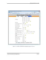
through Hyper Terminal or Telnet or through
browse interface
.
13.1 Physical Connection (RS422)
The color of wires used for RS485 - 2 wire and RS422 - 4 wire are as below:
1. Brown : RX+
2. Black : RX-
3.
Orange : TX+
4. Red : TX-
Note: Please ensure the proper color-coding & signal type while connecting to the actual
Serial device.
13.2 Two Wire Operation: (RS 485)
a) Short TX+ and RX+
b) Short TX - and RX -
Take these two wires and connect to the Device's 2 wires with correct Positive and
Negative polarities.
Select option 2 in the Serial Interface or Telnet mode selection
13.3 Four Wire Operation: (RS 422)
a) Tx+ and TX- of our EAD unit should go to RX+ and RX- of the Serial Device.
b) Rx+ and RX- of our EAD unit should go to TX+ and TX- of the Serial Device.
Select Option 3 for 4 wire operation in Serial Interface or Telnet mode Selection.


