Ethernet Adaptor 01-103
Sparr Electronics Ltd., Bangalore
3
3.3. LED functions
Four LED‟s are located on the top of the unit. One Marked as POWER, which has RED
LED, second one marked as CONNECT which has YELLOW LED, third one marked as
TX which has GREEN LED, fourth one marked as RX which has YELLOW LED The
following table explains their functions.
LED state
Function
Red LED glowing
Power On
Yellow LED blinking
EAD is connected to Ethernet Link
Yellow LED Fast Blinking
IP number conflict with other Device.
Both Red and Yellow LEDs
are glowing
EAD is ready to use.
Yellow LED Blinking when
Ethernet LAN not connected
Will blink for 12.5 seconds and waits
for “Enter” Character from Serial Port
to get in to Configuration mode
Green (TX) LED glowing
Data is transmitting through serial
Yellow (RX) LED glowing
Data is receiving through serial
CONNECT LED will be off when „LOAD FACTORY DEFAULT‟ switch
is pressed continuously for 10 seconds.
3.4. Power Input
There is an Input power socket in the EAD01 MBX model, which can take in 9V AC 300
mA Power where you can plug in the Power adaptor supplied along with the unit. The
MB model has In-built Power supply with a 2 Pin Power CHORD for plugging to Mains
power socket. The Board level product takes in +5 V to +24V DC.
4
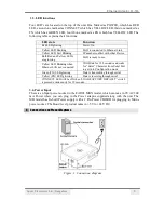
Connection and Pinout Diagrams
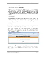
Figure. 1. Connection diagram


