-
18-
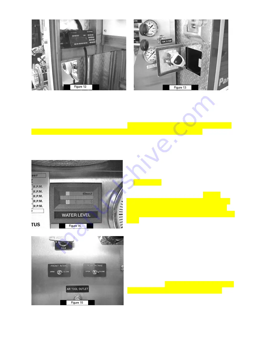
Figures 12 and 13
show the location of the external remote radio control head and
microphone. In order to provide a position convenient to the pump operator and yet
not vulnerable to the elements, the control head and microphone are mounted inside
the “Engineers Compartment”. To avoid requiring the door of this compartment to
remain open during pumping operations, the microphone is mounted to the inside of a
small door which can be opened to access the microphone when pumping. The control
head in the compartment need only be accessed when changing the radio channel or
adjusting the volume on the external speaker which is mounted above the pump
operator’s panel.
The water level gauge shown in
Figure 14
is
located at the top center of the pump
operator’s panel. The water level is indicated
by 20 LED bars with indicators at each quarter
of the scale. As the water level decreases, the
LED’s shut off from right to left. At 25%
remaining water in the tank, the LED’s which
have shut off will begin flashing to alert the
pump operator that the water level is less than
25%.
The front and rear suction inlets to the pump
have air-operated valves. The front and rear
intake switches shown in
Figure 15
, while
appearing to be electrical switches, are
actually air switches which can be immediately
switched from one position to the other. They
are designed to open or close the intake valve
slowly as required by N.F.P.A. standards.


