GB
16
place the canister above the burner channel.
• Only ever connect the appliance to a professionally installed socket! The
power socket should be easy to access and should have a switch.
3.4.1 ASSEMBLY AND SETUP
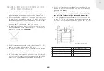
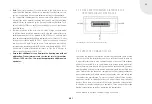
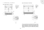
1. Connect the small round low-voltage connector on the mains power unit
to the burner. The connector only fits the socket provided for it on the
underside. This socket is located at the same end of the burner as the
end where the hoses are connected. (Fig. 1)
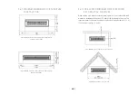
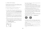
2. Then the hoses supplied must be connected to the burner. Slide the
ends of the hoses firmly home over the connection grommets on the
underside of the burner until the stop. (Fig. 2)
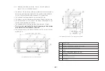
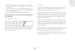
3. Install the Quadra Inside Automatic I SL or II SL in the prefabricated
cutaway in the top plate or table plate. To do this, first lower the instal-
lation frame into the cutaway. Then install the burner in the instal-
lation frame until it locates against the screws in the edges. (Fig. 3)
Ensure that the hoses do not jam or damage the cable. Check to ensure
that the burner insert is horizontal
Please check with a spirit level, but only when the appliance is cold, to
ensure that the burner is horizontal.
The height adjustment screws must be accessible at all times.
The height adjustment screws only have limited adjustment travel. If
no satisfactory levelling is possible in this way, construction measures
(e.g. rebasing of the installation frame) must be employed to improve
the installation situation.
4. Remove the sealing cover from the full ethanol canister. Next, screw
the filler adapter to the container. The hose ends with the metal suc-
tion grommet should be on the base of the canister to ensure that the
container can be emptied as completely as possible.
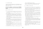
5. Connect the suction hoses to the filler adapters using quick-release
couplings. (Fig. 4)
3.4 COMMISSIONING
The ebios-fire-Quadra Inside Automatic I SL and II SL appliances are sup-
plied with empty delivery hoses to prevent any ethanol from escaping or
evaporating while in transit.
Ensure that the appliance is absolutely balanced. IMPORTANT!
Any failure to observe this point can cause the burner channel to
overflow.
Important information on start-up:
• The circular apertures down the longitudinal side of the burner housing
must remain free, and must not be plugged or narrowed. They act as
inlet air openings.
• Access to the height adjustment screws must be possible at all times.
• The adjustment path of the height adjustment screws is limited. If no
satisfactory levelling is possible in this way, construction measures (e.g.
rebasing of the installation frame) must be employed to improve the
installation situation.
• During first-time operation (commissioning), the hose is still empty. If
the ignition interval fails, it is possible that insufficient ethanol is left in
the burner channel.
• Ensure that the hoses do not bend excessively while being connected
and routed. Always avoid nip and chafing points and tensile stresses.
• Never secure the hoses to the outside of the burner housing. Instead,
leave them hanging free.
• Pull the quick-release couplings gently to check that they are firmly
connected to the filler adapters.
• Check all hose connections to ensure that the hose clamp is positioned
correctly. It must not be possible to pull the hoses off their grommets by
pulling them gently.
• The ethanol canister must always be set up under the burner. Never


