GB
18
4.5 INSTALLATION OF THE CONVECTION AIR
SOCKETS
In order to install the circulation pipes (convection air), initially break out the
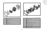
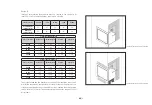
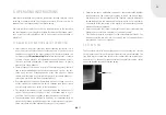
dummy covers and then screw on the two sockets as shown (see Fig. 9a)
using the self-tapping screws provided. Alternatively, these screws can be
screwed from the inside of the convection air jacket out-wards. In order to
redirect the airflow volume, the flaps on the flow control covers at the top
front of the convection air jacket need to be pushed into the cut-out slots
(see Fig. 9b).
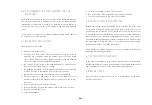
To alter the airflow in the pipework, the size of the baffle plate at the nomi-
nal failure point can be reduced.
Bend when breaking:
corresponds to approx. 50% airflow vol-
ume via the connected pipe system and
approx. 50% in the installation room.
Without any changes:
corresponds to approx 70 % airflow vol-
ume via the connected pipe system and
approx. 30% in the installation room.
4.6 CONNECTING A HOT AIR BLOWER
Not valid for linear cassette XS 500!
If the fireplace cassette has been ordered with a hot air blower then you
only need to connect the plug to a properly earthed electricity socket. The
following steps should be carried out for maintenance / inspection of the
hot air blower:
1. Dismantle the cover (see 4.2)
2. Remove the firebox door (see 4.7)
3. Remove the firebox lining (see 4.9)
4. The blower is accessible after the
inclined rear wall has been dismantled.
In order to retrofit a hot air blower, carry out the previously described steps
numbered 1 to 3 and continue with steps 4b to 4g.
4b. Remove the firebox
4c. Installing the hot air blower involves the following components:
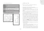
- connection cable set, blower cable, speed regulator, cylindrical fan
and cable gland, Temperature sensor
4d. Cut out the pre-cut section of the convection air jacket on the lower
left side using a hand saw. The metal plate can then be broken out of
the convection air jacket. The speed regulator will be positioned in this
section at a later stage.
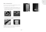
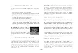
4e. Now assemble the blower onto the
fixing bracket (see picture) and install
it at the middle / bottom of the convec-
tion air jacket.
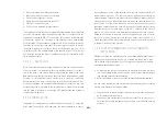
4f. In addition, attach the temperature
sensor provided to the blower bracket.
Attach the temperature sensor here
Predetermined breaking point, pre-stressed
Fig.9a
Abb.9b
Summary of Contents for L 800
Page 1: ...GB Installation and Operating Instructions Linear Fireplace Cassettes...
Page 34: ...GB 34 NOTES...
Page 35: ...GB GB GB 35...


