background image

GB

GB

 19

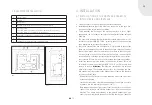
4g.  Connect the cable wires to the terminals on the blower as shown and 

to the control box for the speed regulator.

After the cables have been connected, check and ensure proper function-
ality before finishing the installation. The cables must be fixed using the 
holding flaps. The flaps can either by pressed in from the outside or levered 
out from the inside. Once the cable has been pushed under the flaps, the 
flaps must then be pushed down lightly onto the cable.

PLEASE NOTE: 

Do not press on the flaps too hard because otherwise the 

cable could become damaged!

4h.  Pull the rubber knob off the front of the control shaft and twist off the 

nut and ring washer. The control shaft is inserted through two holes in 
the frame when installing the frame. It may be necessary to order a 
new cassette frame if the existing one does not have any corresponding 
holes

4.7  DISMANTLING AND INSTALLING THE FIREBOX 

DOOR

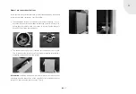
Please follow the following steps to dismantle / install the firebox door. 
Take care when carrying out these tasks as otherwise damage to the casing 
/ door cannot be ruled out. We recommend protecting the casing / metal 
plates with an overlay.

Dismantling:

1.  Use a screwdriver or a similar tool to 

remove the safety clasp on the stop-per 
side (hinge side) of the door.

2.  Swing the door open. Then tighten the 

Allen screw on the lower hinge with a 3 
mm Allen key.

3.  Take hold of the door at the bottom. 

Raise the door a little with a light lifting 
movement so that the lower pin of the 
hinge is exposed.

Blower connection cable

Mains supply

Summary of Contents for L 800

Page 1: ...GB Installation and Operating Instructions Linear Fireplace Cassettes...

Page 2: ...otional level creating feelings of security and comfort To ensure this is achieved we recommend that you carefully read these operating instructions so that you can become quickly and comprehen sively...

Page 3: ...needing protection 13 3 7 Expansion joint between the casing and the fireplace cassette 13 3 8 Combustion chamber design 13 3 9 Example installation 15 4 Installation 15 4 1 Installation of the firepl...

Page 4: ...the outer casing of the fireplace cassette can become very hot Risk of burning Never allow these groups of people to touch or use a fireplace cassette without supervision when a fire is lit or has jus...

Page 5: ...ncrete vermiculite Primary and secondary airflow systems Self closing firebox door with a high temperature resistant ceramic glass panel Heat resistant gloves Type plate mounting location see 5 2 1 2...

Page 6: ...1 2 Exhaust gas systems residential chimneys Fireplaces may only be installed in rooms and locations where no danger results from their position structural conditions and type of use The sur face are...

Page 7: ...oved for multiple installations 2 3 TECHNICAL DATA DIMENSION SHEETS The following information has been taken from the testing report and cor responds to the testing conditions Fireplace cassette XS 50...

Page 8: ...H 130 150 150 150 150 I 352 412 442 472 502 J 100 convection air openings 125 Dimensions Linear cassettes Linear XS 500 mm Linear S 600 mm Linear M 700 mm Linear L 800 mm Linear XL 900 mm K 400 566 66...

Page 9: ...Optional convection air sockets 100mm 1 Cassette frame 60 80 100 mm 2 Firebox door with ceramic glass 3 Firebox lining 4 Firebox 5 Inspection maintenance openings 6 Exhaust gas sockets rotatable vert...

Page 10: ...the position of the operating handle 2 7 GENERAL REQUIREMENTS FOR THE USE OF FIREPLACE CASSETTES IN EXISTING FIREPLACES The fireplace cassettes are suitable amongst other things for retrofitting into...

Page 11: ...ot be closed Ensure that there is sufficient combustion air minimum 360 m per hour and m of the firebox opening The fireplace cassette can be connected to a flexible exhaust gas flue which is fed thro...

Page 12: ...nents The insulation thicknesses listed are based on the reference insulation material rock wool according to AGI Q 132 Silicon based insulation material can also be used with the relevant building ap...

Page 13: ...s to be reduced significantly 3 7 EXPANSION JOINT BETWEEN THE CASING AND THE FIREPLACE CASSETTE There must be no direct connection between the fireplace cassette and the casing An expansion joint is t...

Page 14: ...200 mm 60 mm XL 900 40 mm 60 mm 200 mm 60 mm Rock wool mats to AGI Q 132 Linear cassette Setup floor Mounting wall Ceiling Side wall XS 500 0 mm 50 mm 50 mm 60 mm S 600 0 mm 160 mm 120 mm 80 mm M 700...

Page 15: ...o prevent fires and deflagration it is important to ensure that there are no dangerous deposits in the exhaust gas collection chamber These critical areas must be constructed in such a way that soot p...

Page 16: ...additional thermal protection e g air deflector plate when they are within the thermal radiation field or are located in the area of the cassette s thermal air convection field This is particularly i...

Page 17: ...sulated from the room s air 4 4 INSTALLING OR DISMANTLING THE FIREBOX INTO FROM THE CONVECTION AIR JACKET The firebox can be dismantled from the convection air jacket in its installed state Reasons fo...

Page 18: ...blower then you only need to connect the plug to a properly earthed electricity socket The following steps should be carried out for maintenance inspection of the hot air blower 1 Dismantle the cover...

Page 19: ...he control shaft is inserted through two holes in the frame when installing the frame It may be necessary to order a new cassette frame if the existing one does not have any corresponding holes 4 7 DI...

Page 20: ...to the fixture move the door a little swivel the door 3 Loosen the hexagonal socket on the lower hinge with a 3 mm Allen key 4 Close the door and then push the safety clasp back onto the pin 4 8 INSTA...

Page 21: ...ith cross slot Ensure that you initially screw the screws in loosely Tighten then only once all of the screws are screwed in 3 The exhaust gas connection is inserted into the exhaust gas socket This i...

Page 22: ...L XL Linear XS 500 mm Linear S 600 mm Linear M 700 mm Linear L 800 mm Linear XL 900 mm 1 1 2 1032854 1017402 1017404 1017406 1017408 2 2 1017403 1017405 1017407 1017409 3 2 2 1032859 1017459 1017459...

Page 23: ...e appliance must not be operated with the appliance door left open except as directed in the instructions The fireplace cassette may only be operated when the firebox door is closed The door must also...

Page 24: ...a good level of room ventilation during this burning process Open all doors and windows to the outside Please note minor expansion or stress noises can occur during heating or cooling of the fireplac...

Page 25: ...f required leave the fire box door open by approx 3 5 cm The fire should now light burning brightly and intensively 8 When the kindling wood is burning well add smaller hardwood logs or larger softwoo...

Page 26: ...mod ern houses built after 1990 However the old information for room heating capacity can still be of interest as a comparative value or for use with older building structures that do not yet correspo...

Page 27: ...transitional period meaning when the outside temperature is still high above approx 15 C or during unfavourable weather conditions katabatic winds etc it is possible to experience disruption to the ch...

Page 28: ...clear as pos sible the less visible the exhaust gas appears the better the burning process Wood originating from Europool palettes Waste household rubbish or old clothing Paper paper briquettes carton...

Page 29: ...leaned in a cold state Please note that cleaning can lead to soiling of the installation room and your clothing We recommend that you protect the area around the opening to the fire place from soiling...

Page 30: ...be easily cleaned using standard fireplace glass cleaner which you can also obtain from your specialist dealer The glass fibre seals should not be soaked with cleaning fluids Finally wipe the glass p...

Page 31: ...es on or may pass on to its customers in a particular case 8 2 GENERAL INFORMATION This quality manufactured product is state of the art The materials used were meticulously selected and are constantl...

Page 32: ...hanged colour or other aspects due to ther mal stress Improper transport and or incorrect storage Improper handling of fragile components such as glass and ceramics Improper handling and or use Lack o...

Page 33: ...rranty claims arising in a particular case 8 10 NOTE Your specialist dealer contractor will gladly advise and assist you in matters not covered by our warranty terms and conditions and undertakings We...

Page 34: ...GB 34 NOTES...

Page 35: ...GB GB GB 35...

Page 36: ...ndial para su sal n Het merk van wereldformaat voor uw woonkamer wiatowa marka do Pa stwa salonu 1 D Ihr Fachh ndler UK Your specialist dealer F Votre revendeur sp cialis IT Il vostro rivenditore spec...

Reviews: