- 23 -
No claim is made as to the completeness of this list of regulations.
Fireplaces should only be installed in rooms and at locations where the
position, structural conditions and type of use will not create any hazards.
The floor area of the room where the fireplace is installed must be of such
a type and size that the fireplace can be correctly operated.
During installation, connection and operation of the H
2
O fireplace insert,
always follow and apply all the requisite national and European
standards and local regulations (DIN, DIN EN, regional building
regulations, German state heating regulations, etc.).
HeizAnlV:
German Heating Systems Regulation
FeuVo:
(German State heating Regulation) Heating
Regulation of the relevant German state
1. BlmschV
(German Emissions Regulation)
First Decree enacting ther German Federal
Emissions Protection Act
EnEV
German Energy Saving Regulation
TROL
Technical Rules of the Tiled Stove and Air
Heating Building Trade (ZVSHK)
DIN 1298 /
EN 1856:
Connecting pieces for firing systems
DIN EN 13229
Fireplace
inserts, including open fireplaces, for solid fuels
DIN EN 50165
Electrical equipment of non-electrical devices
for domestic use and similar purposes – Safety
requirements
DIN EN 13384
Calculation procedure for flue gas systems
DIN 18160-1/2
Flue gas systems / domestic chimneys
DIN EN 12828 /
DIN 4751
Heating systems in buildings
Planning of hot water installations
LBO
The building regulations of the German state in
question
VDI 2035
Water conditioning for heating systems
- 24 -
2.2. Electrical connection
Full electrical installation of the individual components of the heating
system may only be carried out by an authorised specialist company. All
the work must be carried out according to the VDE Regulations (e.g. VDE
0105, VDE 0116, VDE 0100 etc.) and the technical connection require-
ments of the local power supply company.
2.3. H
2
O fireplace insert connections
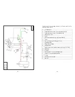
The connections for the safety heat exchanger, the return and the rear
bleed valve are located on the rear and can always be accessed through
an inspection opening
(see Fig. 2a-2f)
via the combustion chamber. The
connections for the feed, the front bleed valve and the immersion sleeves
for the temperature sensors are all located at the side on the flue gas
collector
(see Fig. Fig. 2a-2f
).
These require an opening to be provided in the fireplace cover to obtain
access. For transport purposes the connections are provided with
transport protection devices, which must be removed during installation.
The connections are clearly marked and must not be used for any other
purpose. Equally, the integrated safety device (safety heat exchanger)
must not be used for heating water. We recommend the use of straight or
angled radiator screw connections for the pipe connections.
If the protective anode (only Varia H2O XL and XXL) is installed in open
heating systems, make sure it is accessible so that it can be easily
replaced. The length of the anode must not exceed 30 cm (folding insert)
from the first thread.
When installing the Varia Ah H
2
O / A-FDh H
2
O in an existing heating
system we recommend a minimum nominal pipe width for heating pipes
of: copper pipe, min. 28 x1.0 mm or steel pipe, min. 1” (DN25, 33.7 x
3.25 mm). Plastic pipes or composite pipes must not be used inside the
heat chamber. If ‘temperature-resistant’ gaskets (>140°C) are used on
metal pipes (press systems), these pipes must not be fitted within the
radiant area of components carrying flue gas (distance of 200 mm). As a
general rule, though, after dimensioning they should be connected up by a
specialist company.
Summary of Contents for Mini Z1 H2O
Page 5: ...9 Mini Z1 H2O Fig 1a 10 Mini Z1 H2O XL Fig 1b...
Page 6: ...11 Mini Z1h H2O XL Fig 1c 12 Varia 1V H2O Fig 1d...
Page 7: ...13 Varia 1Vh H2O Fig 1e 14 Varia 1V H2O XL Fig 1f...
Page 8: ...15 Varia 1Vh H2O XL Fig 1g 16 Varia 1V H2O XXL Fig 1h...
Page 9: ...17 Varia 1Vh H2O XXL Fig 1i 18 Varia 2Lh 2Rh H2O Fig 1j...


