- 33 -
For this version the following additional information must be borne in mind
when performing installation.
The TROL guidelines
regarding the free cross-
section of the vent openings
and the maximum supply air
temperatures of 75°C must
always be followed.
Lockable circulating and
supply air openings are not
recommended. This is to
ensure that no heat
accumulates inside the
heating chamber.
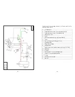
(Fig. 3)
If the vent pipe has been
dismantled on the installa-
tion site to transport it, for
example, make sure that for
subsequent assembly the
copper pipe in the lower
area rests fully against the
copper rail and the body. The tightness of the screw connection on the
head section and correct seating of the heat insulation must then be
checked.
A
Temperature sensor for the ½” thermostat switch and ½” overheat
discharge valve
B
Vent pipe with isulation
C
Vent pipe with copper rail
D
filling and drain fittings DN 15 (1/2”) optional
Fig. 3
- 34 -
2.6. Safety valve
A component-tested safety valve (e.g., Syr type 1915), with a maximum
response overpressure of
3.0 bar
must be installed
in the feed pipe
in
the immediate vicinity of the H
2
O fireplace insert. During installation,
attention must be paid to the manufacturer’s specifications (including
ambient temperature) for the safety valve. A shutoff device must not be
incorporated in the system between the safety valve and the H
2
O fireplace
insert as it could prevent the safety device from operating. Furthermore,
all the required safety devices must be integrated throughout the system
in such a manner as to ensure non-hazardous operation. A separate
safety valve must still be fitted, even if there is one elsewhere in the
system (make sure you comply with TRD 721).
2.7. Load unit
Generally speaking, the H
2
O fireplace insert may
only
be operated with a
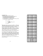
suitable load unit. During operation the return temperature must be at
least 55°C. On the Varia Ah H
2
O and Varia A-FDh H
2
O the return
temperature must be at least 60°C.
To ensure this temperature is achieved, a circulating pump must be
installed in such a manner that it does not cut in until a water temperature
of 60-65°C has been reached in the heat exchanger. This must be
implemented using the
pump thermostat
(supplied, e.g., JUMO
heatTHERM or Afriso) (see section 3.9).
To avoid dropping below local dew points and resulting deposits on the
water heat exchanger, a regulated load unit must generally be installed.
The longer the pipe run between the load unit and the fireplace insert, the
longer the temperature in the fireplace insert remains below the dew point,
as the heating water first has to be heated when the system is fired up.
We therefore recommend fitting the load unit in the immediate vicinity of
the fireplace insert, ensuring it is readily accessible.
Please note:
If there is no load unit fitted or it is not operating properly,
we cannot accept claims under warranty or general liabil-
ity for operating faults or corrosion damage (soot build-
up, deposits, etc.) on the water heat exchanger or on the
chimney, etc.
Summary of Contents for Mini Z1 H2O
Page 5: ...9 Mini Z1 H2O Fig 1a 10 Mini Z1 H2O XL Fig 1b...
Page 6: ...11 Mini Z1h H2O XL Fig 1c 12 Varia 1V H2O Fig 1d...
Page 7: ...13 Varia 1Vh H2O Fig 1e 14 Varia 1V H2O XL Fig 1f...
Page 8: ...15 Varia 1Vh H2O XL Fig 1g 16 Varia 1V H2O XXL Fig 1h...
Page 9: ...17 Varia 1Vh H2O XXL Fig 1i 18 Varia 2Lh 2Rh H2O Fig 1j...


