- 37 -
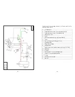
The connection is made as shown in Fig.
4a
and
4b
.
Fig. 4b
Fig. 4a
- 38 -
1 The blue wire is the connected phase (L`) and is phase wired to the
circulating pump or load unit.
2 The green-and-yellow wire is wired to the protective conductor
(earth) (PE) of the mains supply.
3
The brown wire is wired to phase (L) of the mains supply.
4
Thermostat pump control electrical connection
5 Pump control thermostat (e.g. Afriso), with approx. 3.0 m connecting
cable 2x0.75 mm
2
6
Return temperature indication (circulating pump)
7
Terminal 1 not needed
8
Phase (L) brown wire
9
Connected phase (L`) blue wire
2.10. Incorporation into a heating system
Please note
: The H
2
O fireplace insert may only be installed in a complete
system after detailed planning for the entire heating system according to
relevant best industry practice and safety standards.
The correct dimensioning of the pumps, fittings, pipework, buffer storage
tank and safety components, such as the safety valve and expansion
vessel, is the responsibility of the design office and/or of the company
carrying out installation.
Note that very high water outputs of approx. 20 kW can occur briefly
during the combustion phase. The heating system should be dimensioned
to take account of this.
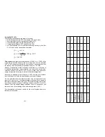
The following calculation example may be helpful for dimensioning the
buffer storage tank:
Summary of Contents for Mini Z1 H2O
Page 5: ...9 Mini Z1 H2O Fig 1a 10 Mini Z1 H2O XL Fig 1b...
Page 6: ...11 Mini Z1h H2O XL Fig 1c 12 Varia 1V H2O Fig 1d...
Page 7: ...13 Varia 1Vh H2O Fig 1e 14 Varia 1V H2O XL Fig 1f...
Page 8: ...15 Varia 1Vh H2O XL Fig 1g 16 Varia 1V H2O XXL Fig 1h...
Page 9: ...17 Varia 1Vh H2O XXL Fig 1i 18 Varia 2Lh 2Rh H2O Fig 1j...


