- 53 -
2.11. Chimney connection / connecting piece
The H
2
O fireplace insert is connected to the chimney by means of
connecting pieces of sheet steel approx. 2 mm thick. These must conform
to DIN 1298 or DIN EN 28160 or the country-specific regulations
regarding the chimney/flue gas system. Care must be taken to ensure that
the flue gas pipe is laid over the shortest distance, rising to the chimney.
As far as possible, the flue gas pipe should not involve any bends or
detours around objects in its path. Furthermore, the flue gas pipe must be
connected to a bricked-in wall lining on the chimney and sealed. If
necessary, the flue gas pipe must be secured with clamps to ensure
adequate fixing. The connecting pieces must be sealed as necessary. If
the flue gas pipe runs through components made of combustible
materials, the flue gas pipe must be insulated in accordance with the
relevant regulations. Generally speaking, the connecting pipe must be
installed in such a manner that it may be cleaned at any time. This must
be ensured by providing a suitable number of cleaning openings.
A measuring connection must be provided in an accessible position to
allow the chimney ventilating pressure in the connecting pipe to be
checked.
2.12. Height limitation / door stop
Only in the case of the Varia 2Lh/2Rh H
2
O is the vertical sliding door fitted
with a variable door stop. This is factory set to the middle position, i.e. the
opening height is reduced by 50 mm.
If the opening height is to be further reduced (reduction in opening height
by 100 mm) or increased (maximum opening), the stops on both sides of
the door must be converted. These can also be reached through the gap
between the glass and door cover after completion of the heating
chamber.
The procedure for this involves the following steps:
Resetting the stop to maximum opening
1. Close the vertical sliding door so that the fixing screws can be
reached
(see Fig. 6)
2. Unscrew the M5x10 threaded screws on both sides of the unit
using a 4 mm Allen key (spherical head). Fig. 7 view: from below,
between glass and door cover.
- 54 -
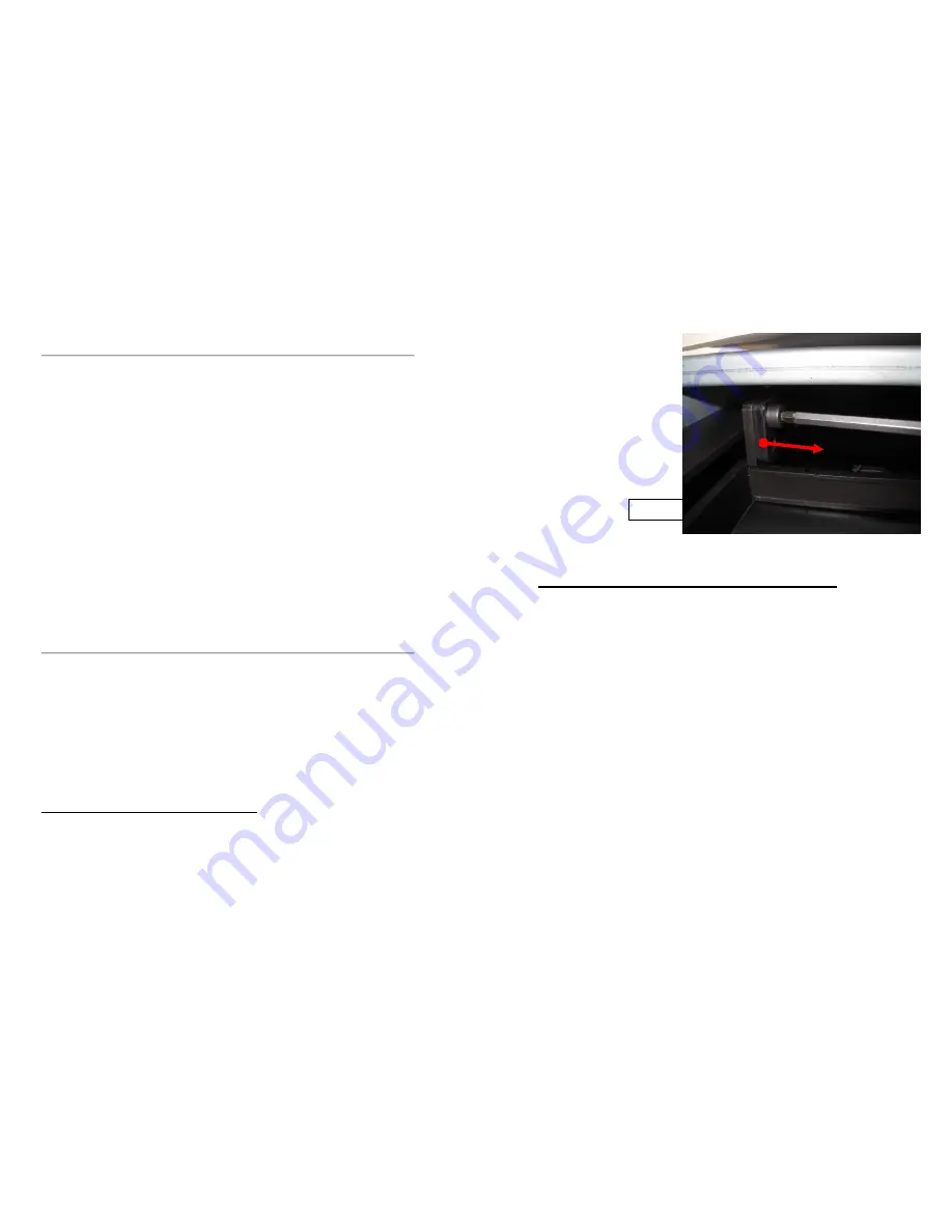
3. Pull off the door
stops in the direc-
tion of the red ar-
row. The stop may
have become
slightly stuck and
will have to be
“levered off” from
below with a flat
screwdriver.
4. The door stops are then no longer required but should be saved.
Resetting the stop to a 100 mm reduced opening height
This setting can be used if the flue gas system is not suitable for open
operation when adding fuel. The air mass flow is reduced by reducing the
opening height of the door.
1.
Close the vertical sliding door so that the fixing screws can be
reached.
2.
Unscrew the M5x10 threaded screws on both sides of the unit
with a 4 mm Allen key (spherical head).
3.
Pull off the door stop in the direction of the red arrow. The stop
may have become slightly stuck and will have to be levered off
from below with a flat screwdriver.
4.
Insert the door stop with the long lug facing the front of the unit.
N.B. The door stops must not be swapped over by mistake.
Example on the Varia 2Rh H
2
O:
Abb. 6
Summary of Contents for Mini Z1 H2O
Page 5: ...9 Mini Z1 H2O Fig 1a 10 Mini Z1 H2O XL Fig 1b...
Page 6: ...11 Mini Z1h H2O XL Fig 1c 12 Varia 1V H2O Fig 1d...
Page 7: ...13 Varia 1Vh H2O Fig 1e 14 Varia 1V H2O XL Fig 1f...
Page 8: ...15 Varia 1Vh H2O XL Fig 1g 16 Varia 1V H2O XXL Fig 1h...
Page 9: ...17 Varia 1Vh H2O XXL Fig 1i 18 Varia 2Lh 2Rh H2O Fig 1j...


