- 59 -
5. Cleaning and maintenance
For cleaning, please also refer to the notes in the operating manual for the
fireplace insert. The notes in this installation and operating manual relate
only to the cleaning of the heat exchanger of the H
2
O fireplace insert.
Please note that cleaning may result in dirtying of the room in which the
unit is installed, as well as of clothing worn. We recommend that you
protect the area around the fireplace insert opening from getting dirty by
means of a plastic or fabric sheet
.
5.1. Cleaning the heat exchanger
It is essential that the heat exchanger be cleaned. Only if the heat
exchanger is cleaned and maintained regularly and properly can it operate
fully effectively. Generally speaking, cleaning must be carried out when
the unit is cold.
Since the heat exchanger cools the flue gases from the H
2
O fireplace
insert directly, and this is bound to result in deposits on the heat exchang-
er surfaces, these must be regularly cleaned with the brush supplied. The
frequency of cleaning depends on several factors (intensity of use,
duration of combustion, fuel, chimney draught, etc.) and is impossible to
state absolutely. We recommend that cleaning be carried out about every
4 weeks. The cleaning intervals must be adapted to local conditions.
When dry firewood is used and if our recommendations are followed, the
cleaning intervals can be significantly extended. After the end of the
heating season, thorough cleaning of all the components is required.
The heat exchanger must generally be cleaned through the combustion
chamber of the fire cell. This requires opening the hearth door and
removal of the flame deflector plate (flame baffle plate) from the combus-
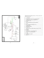
tion chamber. The thermally actuated flue gas valve is then removed
through the combustion chamber
(see Fig. 7a).
To do this, hold the valve
by the handle, tilt it slightly and pull down to remove. Residues may only
be removed from the thermal flue gas valve with a cloth or brush. During
this operation, no pressure should be exerted on the four wings of the flue
gas valve as this could impair operation.
- 60 -
The heat exchanger tubes and the central duct as well as the outer
surfaces of the heat exchanger and the smoke trap must be cleaned with
the brush supplied or with a hand brush. The deposits will then automati-
cally fall into the combustion chamber and can be removed from it using
items generally available on the market (an ash shovel, ash broom or ash
vacuum cleaner).
After cleaning, assembly is carried out in the reverse order. First, insert
the thermal flue gas valve (introduce obliquely from below and place on
the supports). Then insert the flame baffle plate so that the flue gas gap is
A
support
B
automatic flue gas valve with handle
A
heat exchanger tubes
B
flue gas valve handle
Fig. 7a
Fig. 7b
Summary of Contents for Mini Z1 H2O
Page 5: ...9 Mini Z1 H2O Fig 1a 10 Mini Z1 H2O XL Fig 1b...
Page 6: ...11 Mini Z1h H2O XL Fig 1c 12 Varia 1V H2O Fig 1d...
Page 7: ...13 Varia 1Vh H2O Fig 1e 14 Varia 1V H2O XL Fig 1f...
Page 8: ...15 Varia 1Vh H2O XL Fig 1g 16 Varia 1V H2O XXL Fig 1h...
Page 9: ...17 Varia 1Vh H2O XXL Fig 1i 18 Varia 2Lh 2Rh H2O Fig 1j...


