background image

GB

GB

 5

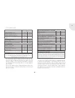
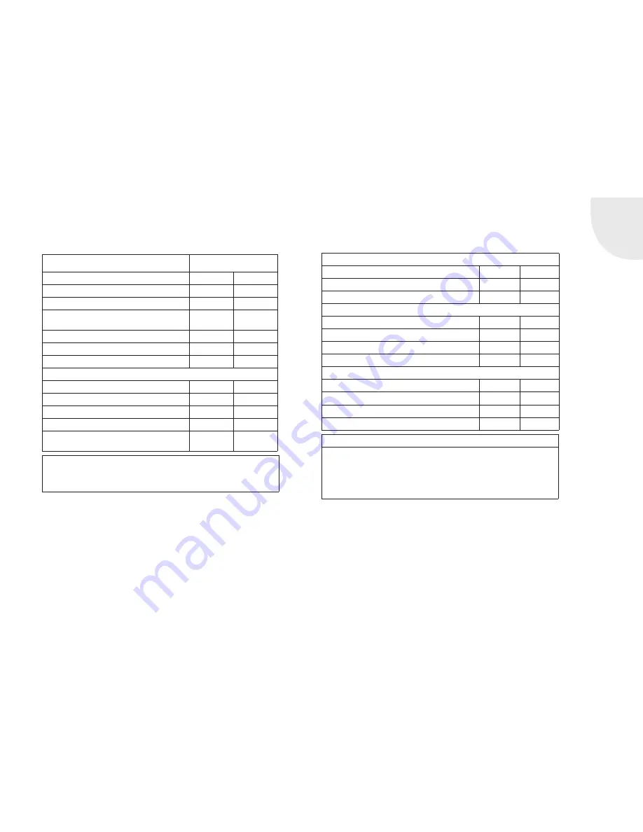
1.2 TECHNICAL DATA

Nova F

Weight (empty, without accessories)

190

kg

Nominal power with heat recovery section*

10

kW

Average heating gas temperature at the duct

355

°C

Average flue gas temperature downstream of the heat recovery 
section

225

°C

Necessary min. delivery pressure**

12 

Pa

Mass flow of flue gas

9,2

g/s

Wood feed quantity with nominal heat output/maximum

3,7

kg/70min

For other fill quantities:

Maximum possible feed quantity

8

kg/60min

Triplet values for 8 kg/60 min:

15

Pa

Average flue gas temperature at the duct

610

°C

Mass flow of flue gas

26

g/s

Average flue gas temperature at duct downstream of the heat 
recovery section

395

°C

Between the triplet values after test (3.7 kg) and the max. fill quantity of 8 kg, interpolation is possible. 

The draught length must be determined by the stove fitter based on the conditions, materials and 

design. An estimate can be made using 50-80 K/m draught length. 

This means that 610°C - 180°C = 430 K / 60 K = ~ 7 m

*   The specified values represent the mean value over a combustion. These 

values occur under test conditions with nominal heat output, if in 70 min 
a quantity of approx. 2.7 kg of dry pieces of beech wood is burned and 
the Spartherm metallic coasting temperature box (coasting temperature 
unit) is installed.

**  Pressure at the heating insert duct. Increased delivery pressures must be 

reduced to less than 25 Pa through suitable measures, such as a draught 
regulator or a damper.

Necessary minimum insulation thicknesses (Silca 250 KM)

Attachment wall (side / rear)

mm

100

Ceiling

mm

160

Setup floor (only under the metallic coasting temperature box

mm

20

Necessary minimum distances to heating chamber / components

Convection chamber (side / rear) to insert

mm

100

Insert to the setup floor

mm

140

Heat recovery section to the wall of the heating chamber

mm

100

Connecting line to the heating chamber ceiling

mm

200

Minimum distances in the radiation areas of the view pane

Flammable parts

mm

800

Flammable parts behind a radiation protection element

mm

400

Area of the non-flammable floor covering to the front

mm

500

Area of the non-flammable floor covering to the side

mm

300

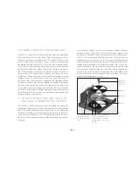
Sheet metal radiation protection element

A sheet metal radiation protection element must be provided at the depth of the heating insert 1.0 m x 
1.0 m 25 cm above the upper edge of the setup floor between the heating insert and the heating chamber 
wall. Alternatively, the distance between the heating insert and heating chamber wall can be increased to 
130 mm, and the insulation thickness can be increased to 120 mm. If the metallic coasting temperature 
box (coasting temperature unit) is used, a sheet metal radiation protection element or insulation 20 mm 
in thickness must be provided under the unit‘s base area.

The thicknesses of thermal insulation material are determined with open 
air grates in the heating chamber, in accordance with DIN EN 13229. If a 
closed heating chamber should be created, the thermal insulation material 
thicknesses must be increased in the verification procedure. When using the 
tested external firing unit, it must be fastened inside of other components 
with suitable 100 mm fire protection insulation (see Material specification, 
minimum insulation thicknesses).

Summary of Contents for Nova F

Page 1: ...GB Installation and Operating Manual Nova F...

Page 2: ...ustomers emotions and speak to feelings such as security and comfort In order to be successful we recommend that you read these installation instructions care fully in order to quickly become thorough...

Page 3: ...llation of S Thermatik motor air box 9 2 5 Changing the door stop 9 2 6 Combustion chamber lining 11 3 Initial commissioning 12 4 Operation 12 6 Fuel 13 7 Rating plate 13 8 General warranty terms and...

Page 4: ...cified in this manual see technical data OUR HEATING INSERT HAS BEEN TESTED IN ACCORDANCE WITH DIN EN 13229 AND SATISFIES THE REQUIREMENTS STIPULATED IN THE CONSTRUCTION PRODUCTS DIRECTIVE DECLARATION...

Page 5: ...ear mm 100 Ceiling mm 160 Setup floor only under the metallic coasting temperature box mm 20 Necessary minimum distances to heating chamber components Convection chamber side rear to insert mm 100 Ins...

Page 6: ...GB 6 Fig 1b Nova F with front panel and external firing unit Fig 1a Nova F with wall penetrating element wall penetrating element wall penetrating element...

Page 7: ...the respective German Federal State 1 BlmschV First Ordinance on the Implementation of the Federal Immission Control Act EnEV Energy Savings Ordinance TR OL Regulations of the German Tiled Stove and A...

Page 8: ...ivery it may be necessary to mount the rotating disc through the combustion chamber in the floor area of the tiled stove e g device design with S Thermatik Installation is not executed in the factory...

Page 9: ...o produce the air connection the four hexagon socket screws must now be unscrewed Then the connecting lever must be lifted off the air adjustment lever With this step the entire air control unit is fr...

Page 10: ...opposite side where a bore is provided 3 Insertion of the new door Insert the new door to do this slide the door with the upper pivot hinge into the provided bores Then open the door 90 and fit the l...

Page 11: ...rough top side The front baffle plate 10 must be inserted in the same manner The combustion chamber lining is removed in the reverse sequence Important When removing and installing you must ensure th...

Page 12: ...e confirming proper installation and proper adjustment function of all control components and safety components must be given to the owner operator of the system Moreover the operator must be instruct...

Page 13: ...t make wood During the lifetime of the tree sunlight is chemi cally captured Solar energy is stored in lignin and cellulose When the wood is burned that energy is released again For further informatio...

Page 14: ...ty on elevating mechanisms operating devices such as handles adjustment levers shock absorbers electronic and electrical components such as exhausters gover nors original spare parts all purchased par...

Page 15: ...s the right either to rectify the defect or to replace the unit free of charge Remediation of defects shall take precedence This warranty undertaking expressly does not cover further compensation exce...

Page 16: ...for leaks yes no All safety devices thermal discharge safety device safety valve membrane expansion vessel checked yes no yes no Enter temperatures between insert and return flow boost Return flow te...

Page 17: ...GB GB GB 17 NOTES...

Page 18: ...GB 18 NOTES...

Page 19: ...GB GB GB 19...

Page 20: ...ndial para su sal n Het merk van wereldformaat voor uw woonkamer wiatowa marka do Pa stwa salonu 1 D Ihr Fachh ndler UK Your specialist dealer F Votre revendeur sp cialis IT Il vostro rivenditore spec...

Reviews: