GB
8
2.2 CHIMNEY CONNECTION / CONNECTING PIECES
The Nova F is connected to the chimney with the connecting pieces made
from steel sheet at least 2 mm thick. These connecting pieces must
satisfy the requirements specified in DIN 1298 and DIN EN 1856-2, and
must be connected to the chimney / flue gas system in accordance with
the requirements specified in DIN 18160 or the country-specific regula-
tions. It must be ensured that the flue gas pipe takes the shortest possible
route upwards towards the chimney. The number of bends in the flue gas
pipe should be kept to a minimum. In addition, the flue gas pipe must
be connected to the chimney with a bricked-in wall lining and sealed.
If necessary, the flue gas pipe must be fastened with clamps to ensure
adequate fixation. The connecting pieces must be sealed if necessary! If
the flue gas pipe is routed through components with flammable building
materials, the flue gas pipe must be insulated as specified in the regula-
tions. The connecting line must always be mounted in such a manner that
it is possible to clean the connecting line at any time. This must be ensured
through a sufficient number of cleaning openings. A gauge connection must
be installed so that it is accessible for determination of the negative chim-
ney pressure in the connecting line.
2.3 INSTALLATION OF ROTATING DISC / AIR ADJUST-
MENT LEVER / SERVOMOTOR FOR S-THERMATIK
After delivery, it may be necessary to mount the rotating disc through the
combustion chamber in the floor area of the tiled stove (e.g. device design
with S-Thermatik). Installation is not executed in the factory because the
star adapter (frictional connection between servomotor and rotating disc),
as well as the servomotor for the S-Thermatik project downwards out of
the device. These components would be damaged through transport and
installation.
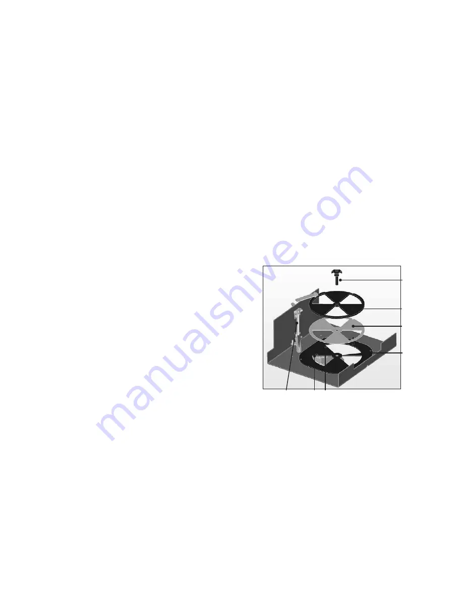
For installation, removal of the front combustion chamber chamotte
( chamotte brick no.: 7 and 8 Fig. 4) and of the combustion chamber floor
are necessary. Installation of the air mechanism must be executed as shown
in Fig. 3a. The air adjustment lever must be in the „closed“ position (air
adjustment lever at the left stop), so that the primary ventilation damper
can be inserted. After installation, the function of the air controller must be
checked before installation of the combustion chamber floor. For this, the
inspection opening in the front chamfer of the combustion chamber bowl
must be opened. Through this opening, it must be possible to determine the
opening of the primary ventilation damper when the air adjustment lever
is in the right position. If the air adjustment lever is turned to the left, the
primary ventilation damper must close.
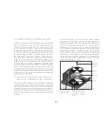
Star adapter
for frictional
connection
Rotating disc
VA slide plate
Bores for holder of the servomotor
(only for S-Thermatik). The support
of the servomotor is installed
through the large cut-out in the
base plate.
Base plate
The bore of the articulated
arm must be fitted on the
bolt of the air adjustment
lever.
Fig. 2
Summary of Contents for Nova F
Page 1: ...GB Installation and Operating Manual Nova F...
Page 17: ...GB GB GB 17 NOTES...
Page 18: ...GB 18 NOTES...
Page 19: ...GB GB GB 19...


