GB
GB
9
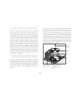
2.4 CONNECTION OF COMBUSTION AIR / INSTALLA-
TION OF S-THERMATIK, MOTOR / AIR BOX
Installation sequence - combustion air connection:
Step 2.4:
Installation occurs in the reverse sequence. During the installation, proper
opening and closing of the rotating disc must be checked! See point 2.3 on
page 7 in this regard.
2.5 CHANGING THE DOOR STOP
If the door stop is to be changed, this is also possible after the overall
system has been completed. For this, a new door must be ordered with
specification of the order number, which then can be replaced thanks to
the universal frame.
To remove the door, the following work steps must be executed:
1. Removal of the „old“ door
a.) First, remove the securing clip on the upper pivot hinge.
Step 1.1:
Unscrew the screws in the combustion chamber floor. If the
combustion chamber lining is already installed, the front sill
brick and the front floor brick must be removed beforehand.
The floor plate has two notches on the rear, behind which
a screwdriver can be placed for levering out.
Step 1.2:
To produce the air connection, the four hexagon socket screws
must now be unscrewed. Then the connecting lever
must be lifted off the air adjustment lever. With this step, the
entire air control unit is free and can be lifted or taken out
of the combustion chamber. The combustion air line can now
be screwed onto the 125 mm or 150 mm ducts below the
galvanised air box.
Step 2.1:
In order to install or remove the servomotor of the S-Thermatik,
steps 1 and 2 as previously described must be executed. Then
the star adapter or the slotted straight pin and the rotating
disc must be taken out followed by the slide bearing. See also
Fig. 2, page 8.
Step 2.2:
After removing the air controller parts, the S-Thermatik motor
is screwed on under the floor of the device.
Step 2.3
:
Then the combustion air connection box must / can be
screwed back on. If the combustion air should be connected
on the connection box, the connection cable of the servomotor
must be inserted through the cable outlet. To reduce input of
air that cannot be shut-off, this cover must be twisted onto the
cable as tightly as possible. We recommend that this „damper“
is secured with temperature-resistant adhesive tape.
Installation sequence - S-Thermatik motor and air box:
Summary of Contents for Nova F
Page 1: ...GB Installation and Operating Manual Nova F...
Page 17: ...GB GB GB 17 NOTES...
Page 18: ...GB 18 NOTES...
Page 19: ...GB GB GB 19...


