GB
GB
29
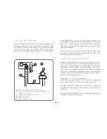
The thermal discharge safety device (e.g. company Watts,
STS20/200) is not preinstalled during the transport and assembly
of the stove for safety reasons. It can be found in the firebox and is
to be installed onto the relevantly labelled connection. Afterwards,
the capillary pipe with adapter is to be screwed onto the thermal
discharge safety device. This is to be tested for a minimum flow
rate of 900 kg/h and approved.
It is essential to observe the following points during installati-
on, to ensure the functionality of the safety device:
•
A flow pressure of at
least 1.5 bar
is to be available at the
cold water supply inlet. This water pressure must be per-
manently guaranteed. Any fluctuations in the water system
pressure are to be excluded. This means that e.g. it is
not
permitted
to use household water provision that is dependent
on the mains electricity voltage!
•
A minimum flow rate of approx. 900 kg/h of water must be gu-
aranteed. It must
not
be possible to shut off this water supply!
All safety-relevant construction components are to be integrated
into the system in such a way that their functionality and leak-tight-
ness can be inspected at any time! The water outlet of the thermal
discharge safety device is to be designed so that an inspection can
be carried out at all times (e.g. via an outlet with a siphon).
The cold water supply pipe is to be rinsed out before commis-
sioning! This will rinse out any soiling that was caused, for exa-
mple, when connecting the thermal discharge safety device. The
manufacturer’s instructions for the thermal discharge safety device
must be observed.
2.2.8.4 THERMAL PUMP CONTROL
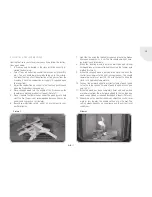
A thermostat switch (e.g. company Afriso) is integrated in the lower
compartment to enable the optimal control of the circulation pump.
It ensures that the circulation pump only starts up at the required
water temperature (> 60°C). Control via the boiler or similar equip-
ment is possible. The maximum contact load for the thermal pump
control is around 10 (2.5) A with alternating current of 250 V AC.
The factory setting for the thermostat is preset to approx. 62°C.
The temperatures are set here for switching the circulation pump
for the load unit (heat charger) on or off when the required water
temperature is achieved or exceeded in the water heat exchanger of
the SENSO M H
2
O. If the local conditions make it necessary then the
temperature can be optionally adjusted by the installation compa-
ny. Depending on the design of the thermostat, this involves either
adjusting the rotary control dial or removing the lower round cover
(D=10 mm). Once the cover has been removed, the temperature
range can be adjusted.
Please note:
In the event of water temperatures below 60°C, this
increases the danger of undershooting the dew point. This can re-
sult in the development of “hard soot”. In addition, this shortens
the cleaning intervals. Therefore, we recommend that the switch-
on temperature is not set to under 60°C but also not greater than
68°C.
Summary of Contents for Passo L
Page 2: ......
Page 3: ...Montage und Betriebsanleitung Kaminöfen Selection ...
Page 54: ...D 52 RAUM FÜR IHRE NOTIZEN ...
Page 55: ...Installation and Operating Instructions for Stoves Selection ...
Page 106: ...GB 52 SPACE FOR YOUR NOTES ...
Page 107: ...Notice de montage et d utilisation pour les poeles Selection ...
Page 158: ...F 52 VOS NOTES ...
Page 159: ...Istruzioni di montaggio e d uso per stufe camino Selection ...
Page 210: ...SPAZIO PER I VOSTRI APPUNTI IT 52 ...
Page 211: ...Instrucciones de montaje y uso de las estufas de le a Selection ...
Page 262: ...ES 52 ESPACIO PARA SUS APUNTES ...
Page 263: ...Montage en gebruikshandleiding Kachels Selection ...
Page 314: ...NL 52 RUIMTE VOOR AANTEKENINGEN ...
Page 315: ...Instrukcja montażu i obsługi pieców kominkowych Selection ...
Page 366: ...PL 52 MIEJSCE NA PAŃSTWA NOTATKI ...
Page 367: ...Руководство по монтажу и эксплуатации печей каминов Selection ...
Page 418: ...РУС 52 МЕСТО ДЛЯ ВАШИ ЗАПИСЕЙ И ПОМЕТОК ...
Page 419: ......

