GB
8
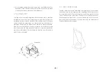
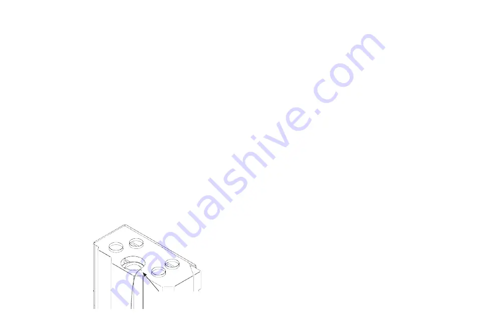
The following procedure is recommended:
• Drill a hole D=10 mm in the convection air housing.
• Insert fastening bolts
• Insert temperature sensor
• Screw the plug connection supplied on to the temperature sensor cable
• Connect the plug connection to the control unit.
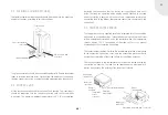
4.6. FIREPLACE COVER DESIGN
The fireplace covering should be designed such that approx. 600 m³/h
circulating air can flow to the blower unit. The accessibility of the built-in
components must be ensured at all times.
Important:
All the convection air housing connecting pieces on the
convection air housing must be fitted with flexible tubes D = 15 cm. This
allows the convection air to be supplied to the room where the fireplace is
or to other rooms via the flexible aluminium air ducts.
4.7. CUSTOMER INSTRUCTION
• The installer must instruct the operator in the functioning and operation
of the S-Vent 100 forced convection system.
5. OPERATING INSTRUCTIONS
These operating instructions apply only to the S-Vent 100 modular forced
convection system. The instructions in the fireplace insert operating manual
must be followed when operating the fireplace insert.
5.1. DESCRIPTION OF FUNCTION
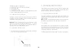
The system is operated via a separate radio remote control. Readiness for
operation is indicated by an operating status display on the control unit, which
shows a red light.
Note:
The modes set via the radio remote control and the set speeds and
temperatures are preserved even if the mains power is switched off.
5.2. MODES
All the functions of the S-Vent 100 forced convection system are controlled
via the radio remote control supplied with the system. There is no need for
operator intervention via the control unit while the system is operating. The
LED indicates transmission of the command.
The following modes can be selected: ‘manual’, ‘automatic’ or ‘proportional’.
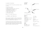
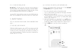
Temperature sensor
with threaded fitting


