16
630359_5
A suitably sized hole will need to be drilled in the steel
convection air jacket to accommodate the flexible shaft to suit
the planned position of the control lever.
The fireplace must be installed on a
non-combustible base
that is suitably engineered to support the weight of the
appliance. We recommend a reinforced concrete slab (min.
100mm thick).Suitable
seismic restraint
must be provided.
This can easily be achieved by screwing or bolting the 4 feet
of the fireplace securely to the concrete slab.
Combustion air
– In addition to providing cavity (convection)
intake air vents it is a requirement to also provide air for
combustion. If taking the combustion air from outside of the
building (Direct vent) through a Ø150mm (165mm OD) pipe
and into the appliance via the optional appliance adaptor
(recommended), ensure that the run of the Ø150mm pipe is
as short as possible and as unrestricted as possible.
Try to use 45° bends in lieu of 90° bends and restrict the total
number of bends to 2. If the pipe is in an area where
condensate may form on the outside then adequate provision
for lagging/insulation of the pipe outer should be planned.
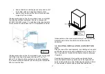
Varia Bh-P7 inlet Varia ASh-P8, A-FDh-P8,
A-FDh-P8 & 2L/R 80h-P7 inlet
It is also advised to make provision for periodic cleaning of the
pipe inner by providing a “rodding eye” or other means of
access. Where the pipe terminates on the outside of the
building it should be suitably protected from water, foreign
matter ingress and rodent/bird/flying insect ingress.
The Ø150mm pipe run
within
the skamo enclosure board
enclosure should be made from a heat resistant material
(galvanised steel, stainless steel etc.). You may transition to
PVC pipe or similar 300mm after the pipe has exited the
Skamotec enclosure.
Providing a means to access each of the pipe joints for future
inspection and cleaning is recommended.
Considerations for positioning the combustion air intake
vent & pipe
•
Ensure that the chimney top and the air intake are
in the same pressure zone. Different zones could
cause problems particularly on windy days.
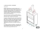
Figure 10
Summary of Contents for Varia 2L 80h-P7
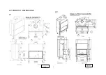
Page 5: ...5 630359_5 2 0 PRODUCT DIMENSIONS 2 1 2 2 Figure 1 Figure 2 ...
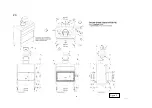
Page 6: ...6 630359_5 2 3 Figure 3 ...
Page 7: ...7 630359_5 2 4 Figure 4 ...
Page 8: ...8 630359_5 2 5 Figure 5 ...
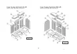
Page 23: ...23 630359_5 Corner L R Varia 2L 2R 80h P7 Double Sided Varia A FDh P8 Figure 23 Figure 24 ...
Page 26: ...26 630359_5 3 7 EXAMPLE OF CAVITY CONSTRUCTION Figure 30 Figure 31 ...
Page 51: ...51 630359_5 ...
Page 52: ...52 630359_5 Data Plate Installer Adhere duplicate data plate here ...


