This is a publication by Conrad Electronic SE, Klaus-Conrad-Str. 1, D-92240 Hirschau (www.conrad.com).
All rights including translation reserved. Reproduction by any method, e.g. photocopy, microfilming, or the capture in
electronic data processing systems require the prior written approval by the editor. Reprinting, also in part, is prohibited.
This publication represent the technical status at the time of printing.
© Copyright 2018 by Conrad Electronic SE.
1587093_V1_0518_02_VTP_m_en
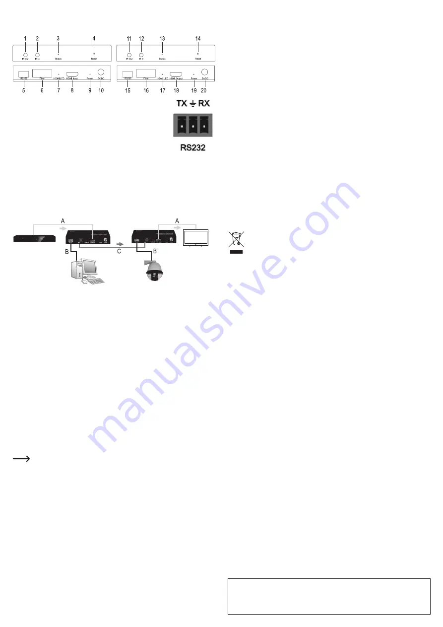
Connections and control elements
a) Transmitter unit (“SENDER”) b) Receiver unit (“RECEIVER”)
1 + 11
Connection “IR Out” for IR sender
2 + 12
Connection “IR In” for IR receiver
3 + 13
LED “Status”
4 + 14
Reset button (recessed)
5 + 15
Screw terminals for RS232 (pin assignment
see image on the right)
6 + 16
Port for optical cable
7 + 17
LED “HDMI”
8
HDMI input (“HDMI Input” port )
18
HDMI output (“HDMI Output” port)
9 + 19
“Power” LED
10 + 20
Screw connector for power supply
Connection example
• For example, you can connect a Blu-ray player to the HDMI input (8) of the transmission
unit (“SENDER”); a suitable monitor/TV/projector to the HDMI output (18) of the receiver unit
(“RECEIVER”). The AV signal (A) is transmitted over the optical cable (C).
• You could use the RS232 screw terminals (5 + 15) to control an appropriate surveillance
camera (for example, alignment, zoom, etc.). Make sure the baud rates on both devices
match. The RS232 signal (B) is transmitted over the optical cable (C).
• The optical ports of the transmitter and receiver units must be connected via an optical cable.
All signals are transmitted over the cable.
• Via the IR transmitter and IR receiver ports (not shown in the image above) IR signals are
sent from an IR remote control, for example, over the optical cable bidirectionally.
Installation
• Install the mounting brackets included to the right and left of the housing first, if you intend
to fasten the transmitter or receiver unit to a suitable surface (such as a wall or a table). Use
the screws included.
• You will need additional mounting material (such as screws and dowels, not included) to
fasten the unit to the mounting surface.
Connection
• First of all, turn off all the devices you are intending to connect.
• Connect the ports of the transmitter and receiver units with the corresponding devices.
Make sure that you do not mix-up the transmitter unit (“SENDER”) and the receiver
unit (“RECEIVER”)!
Likewise, it is also important that you do not confuse the IR transmitter with the IR
receiver. The IR transmitter is smaller than the IR receiver and has a cable with only
one mono jack attached).
• Once the devices are connected, plug the transmitter unit and the receiver unit each into one
of the two power adapters included. The adapters are identical. Therefore, it doesn’t matter
which one you are going to use for a unit. Tighten the lock nut of the plug by hand (do not
use a tool!).
Operation
Once connected and plugged into the voltage/power supply, transmitter and receiver are ready
for operation. Turn all connected devices on.
• The “Power” LED (9 + 19) goes on, if voltage/power is present.
• The “HDMI” LED (7 + 17) goes on, if an HDMI device is connected and signals are being
transmitted.
• The “Status” LED goes on once the transmitter or receiver unit is ready for operation.
• The transmitter or receiver unit are can be reset by means of the recessed reset button
(4 + 14). Use a straightened paper clip, for example, to hold down the button for 10 seconds.
Alternatively, disconnect the power adapter from the device for a few seconds.
• If you are near the receiver unit (“RECEIVER”), you can control the HDMI device connected
to the transmitter unit (“SENDER”) using its remote control.
• If you are near the transmitter unit (“SENDER”) , you can control the HDMI device connected
to the receiver unit (“RECEIVER”) using its remote control.
Troubleshooting
No image
• Turn all devices on.
• Check all cable connections.
• Select the correct input on the television/monitor.
• Use high-quality HDMI cables.
• Disconnect the transmitter and receiver units from the power supply for a few seconds.
HDMI device does not respond to the IR remote control
• Relocate or realign the IR transmitter and IR receiver.
• The product is incompatible with the IR transfer protocol used by your IR remote control.
• Try to hold down the button on your IR remote control a bit longer than usual.
Care and cleaning
• Always disconnect the product from the devices connected before cleaning, unplug the
power adapters from the mains socket.
• The product contains no parts that require servicing. Therefore, do not open/dismantle it.
• Never use abrasive cleaning agents, rubbing alcohol or other chemical solutions, since these
could damage the casing or even impair operation.
• Use a dry, lint-free cloth to clean the product.
Disposal
Electronic devices are recyclable materials and do not belong in the household
waste. Dispose of an unserviceable product in accordance with the relevant statu-
tory regulations.
That way you fulfil your statutory obligations and contribute to the protection of the
environment.
Technical data
a) General information
Ambient conditions ............................ Temperature 0 °C to +40 °C, air humidity 5% to 90%
relative, non-condensing
b) Receiver unit and transmitter unit
Supported resolution ........................up to 1080p/60 Hz
Supported audio format .....................LPCM, 48 kHz
RS232 port ........................................Phoenix
RS232 Baud rate ...............................max. 115200
IR-frequency ......................................38 - 58 kHz
IP-address receiver ...........................192.168.168.56
IP-address transmitter .......................192.168.168.55
Optical port ........................................SC, 6.25 Gbps
Optical cable ......................................SMF, wavelength 1310/1550 nm
Signal range ......................................up to 20 km (depends on optical cable)
Dimensions ........................................132 x 95 x 21 mm (W x D x H)
Weight ...............................................approx. 276 g
c) Power adapters (2 pieces included in the delivery)
Operating voltage ..............................100 - 240 V/AC, 50/60 Hz
Output ................................................5 V/DC, 2 A


