4.
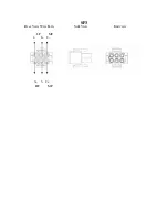
AC mains connection. The mains disconnect of the amplifier is the AC plug.
It must be removed from the AC service to completely remove power from the
amplifier. The AC mains power cord is connected to the front panel through the
blue Neutrik Powercon. The mating cable end connector is NAC3FCA. The gray
Powercon connector is a power outlet that allows looping to adjacent amplifiers.
The looping outlet mating cable connector is NAC3FCB.
Do connect equipment
to the power outlet that exceeds the marked rating of the outlet.
5.
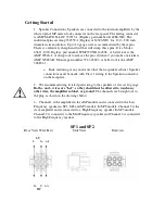
Signal connection. Signal input is through locking XLR connectors. The input
is transformer balanced. If an unbalanced source is connected, make sure that the
signal is connected between pins 2 and 3. The input impedance is 45K Ohms.
III.
Basic Operation
1.
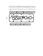
115/230 V switch.
This switch changes the range of voltages accepted by
the amplifier
.
Make sure it is set to the proper range before connected the
amplifier to AC
. Once set to the proper range, the amplifier will regulate the
internal voltages so that output power does not change with supply voltage.
If the
switch position is changed, the fuse must be changed to the proper value as
well
. Some models do not have a voltage selector switch. They must be connected
to the supply indicated on the amplifier markings.
2.
Powering up the amplifier.
Before turning on the amplifier, check to make
sure the voltage selector switch is set to the proper range for your service
.
Connect the input, lower the volume control, and turn on all preceding equipment
in the signal chain.
To turn on power, press the side of the power switch
marked “ON”
. After applying the power, check that the mute switches are in the
“out” position and slowly raise the volume.
3.
LED Indicators. “CLIP” indicates when Channel 1 is clipping. “PROT”
indicates when the power supply protective circuitry has been engaged. It may be
necessary to cycle the power to reset the protective circuitry. “PWR” indicates
that power is present in the amplifier. “SIG” indicates that signal is present at the
input of the amplifier.
4.
Muting switches. These switches mute the individual amplifier channels for
setup and troubleshooting purposes. The channels are unmuted and operational
when the switch is IN.
5.
Volume control. This lowers in the volume in 1 dB steps down to –12dB, then
the steps are larger until the input signal is completely shut off.
6.
Program Select switch. This switch allows the selection between two DSP
programs stored in EEPROM. The AC power must be cycled off and on for the
selected program to be loaded.


