background image

8999146EN: v1 26/02/2020 

4  

Original instructions (ENGLISH) 

Website:  www.spearheadmachinery.com 


Trisaw/Quadsaw 


Spearhead heavy-duty Trisaw and Quadsaws are hydraulic boom mounted sawblade attachments for the 
cutting of trees and branches. Available in three working widths, the 1.5m Trisaw is the smallest machine in the 
range equipped with three belt-driven tungsten carbide tipped sawblades capable of cutting materials up to 
150mm diameter. The larger 2.0m & 2.5m Quadsaw machines are equipped with additional sawblade offering 
the same capabilities as the smaller model machine. 
 
Designed for use on larger model Twiga reach arms and Twiga Carrier loader arms, Trisaw/Quadsaw is the 
ideal machine for farmers, forestry teams and contractors alike.  
 
IMPORTANT: This machine must only be used to perform the tasks for which it was designed, use for any other 
purpose may be dangerous to persons and damaging to the machine. 


IMPORTANT 


This operator’s manual should be regarded as part of the machine.  Suppliers of both new and second-hand 

machines are advised to retain documentary evidence that this manual was provided with the machine. 


This machine is designed solely for ground vegetation control and must not be used for any other purpose.  

Use in any other way is considered as contrary to the intended use.  Compliance with, and strict adherence 

to, the conditions of operation, service, and repair, as specified by the manufacturer, also constitute 

essential elements of the intended use. 


This machine should be operated, serviced, and repaired only by persons who are familiar with its 

characteristics and who are acquainted with the relevant safety procedures. 


Accident prevention regulations, all other generally recognised regulations on safety and occupational 

medicine, and all road traffic regulations must always be observed. 


Any arbitrary modifications carried out to this machine may relieve the manufacturer of liability for any 

resulting damage or injury. 


It is potentially hazardous to fit or use any parts other than genuine 

Spearhead

 parts. 


The company disclaims all liability for the consequences of such use which, in addition, voids the machine 

warranty. 


Summary of Contents for Quadsaw Series

Page 1: ...8999146EN v1 26 02 2020 1 Original instructions ENGLISH Website www spearheadmachinery com Spearhead Machinery Operator Instruction Manual For 1 50m 2 00m and 2 50m cut width ...

Page 2: ...er Name Of Installing Dealer Dealer Address Dealer Signature Date Of Delivery Installation Date Of Warranty Registration IMPORTANT At the point of transfer of ownership record the above information Note the serial number of your machine and always quote it in any communication with us or your dealer The serial number plate is located on the machine mainframe This is particularly important when ord...

Page 3: ...Machinery Directive is supported by the following harmonized standards Directive 2006 42 EC 2006 BS EN ISO 12100 2010 Safety of machinery General principles for design Risk assessment and risk reduction BS EN 349 1993 A1 2008 Safety of machinery Minimum distances to avoid the entrapment with human body parts BS EN ISO 14120 2015 Safety of machinery Guards general requirements for the design and co...

Page 4: ...f the machine Suppliers of both new and second hand machines are advised to retain documentary evidence that this manual was provided with the machine This machine is designed solely for ground vegetation control and must not be used for any other purpose Use in any other way is considered as contrary to the intended use Compliance with and strict adherence to the conditions of operation service a...

Page 5: ...8999146EN v1 26 02 2020 5 Original instructions ENGLISH Website www spearheadmachinery com This page is left blank intentionally ...

Page 6: ...4 2 Use of Warning Signs 21 2 15 Safety Decals 22 2 16 The Machine The Environment 23 2 16 1 Disposal 23 2 17 Proposition 65 24 3 Machine Preparation 26 3 1 Tractor Requirements 26 3 2 Tractor Checks 26 3 3 Lifting The Machine 26 3 3 1 Lifting Equipment 26 3 3 2 Lifting Points 26 3 4 Controls Overview 27 3 5 Machine Attachment 27 3 5 1 Blade Guard 27 3 6 Attaching To The Reach Arm 28 3 7 Blade Cut...

Page 7: ...Machine For Storage Reintroduction Into Work 54 6 Troubleshooting 56 7 Spare Parts 58 7 1 How To Obtain The Correct Spare Part Numbers 58 7 2 Spare Parts Ordering 59 7 3 Dealer Network 59 8 Warranty Policy Information 60 8 1 Limited Warranties 60 8 2 Remedies And Procedures 61 8 3 Limitation Of Liability 61 8 4 Miscellaneous 62 8 5 Registration Of A Demo Machine 62 8 6 Claims Procedure 62 8 7 Dama...

Page 8: ... tipped sawblades capable of cutting materials up to 150mm diameter The larger 2 0m 2 5m Quadsaw machines are equipped with additional sawblade offering the same capabilities as the smaller model machine Designed for use on larger model Twiga reach arms and Twiga Carrier loader arms Trisaw Quadsaw is the ideal machine for farmers forestry teams and contractors alike IMPORTANT This machine must onl...

Page 9: ...Blade Tip Speed 2 76 9 m s 76 9 m s 97 3 m s Motor Hydraulic 40 6cc Hydraulic 40 6cc Hydraulic 40 6cc Flow Rate Twiga Reach Arm 84 87 l min 210 bar 84 87 l min 210 bar 84 87 l min 210 bar Twiga Carrier 45 l min 210 bar 45 l min 210 bar 45 l min 210 bar Drive V belt V belt V belt Cutting Capacity 1 2 150mm 6 150mm 6 150mm 6 Main Application Vertical Cutting Vertical Cutting Vertical Cutting Forward...

Page 10: ...a on the Spearhead manufacturer s plate should always be referred to when requesting assistance and or requiring replacement spare parts This data can identify the machine and its characteristics and specification for its particular time of manufacture certifying that it responds to current regulations For this reason the plate should never therefore be removed nor be used for other purposes if th...

Page 11: ...8999146EN v1 26 02 2020 11 Original instructions ENGLISH Website www spearheadmachinery com This page is left blank intentionally ...

Page 12: ...people are well clear DANGER AVOID WIRE It can be extremely dangerous if wire gets caught up in the machine attachment and every care must be taken to ensure this will not happen Inspect the working area before commencing Remove all loose wire and obstructions and clearly mark those that are fixed so that you can avoid them Any unusual noise from the machine indicates that the blades may have been...

Page 13: ...good condition Refer to Section 2 6 to ensure you have the correct guards fitted for the type of operation being performed WARNING While the tractor is running all personnel should keep well clear of the area around the machine as there are numerous crushing shearing impact dangers caused by the machine operation WARNING Direct the cut material away from the tractor It is important that while oper...

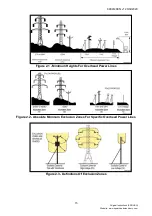
Page 14: ...ximum reach height for your machine mounted on the tractor Always find out the location and route of all Power Lines within the work area Always find out the operating voltage of all Power Lines within the work area Always contact the local Distribution Network Operator DNO who will be able to advise you on the operating voltage exclusion zones the minimum safe working distance and any additional ...

Page 15: ...inal instructions ENGLISH Website www spearheadmachinery com Figure 2 1 Minimum Heights For Overhead Power Lines Figure 2 2 Absolute Minimum Exclusion Zones For Specific Overhead Power Lines Figure 2 3 Definitions Of Exclusion Zones ...

Page 16: ...ts Figure 2 4 PPE Items When working at the work site but off the tractor unit operators are advised to wear a high viz garment 2 6 Cab Guarding DANGER For safe operation it is essential that that all guards must be kept in position on the machine whenever the machine is running Spearhead Machinery disclaim all responsibility for any damage or injury arising as a result of guards being removed or ...

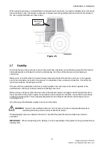
Page 17: ...ows evidence of bearing some load If the tyre lifts then add ballast in the form of wheel weights to the rear wheel of the tractor opposite to the extended arms until the tyre shows evidence of bearing some load Before driving in transport place the reach arm in the transport position and again check that all wheels of the tractor are both on the ground Again it is advisable to have a helper to ch...

Page 18: ...may try to lift the front axle This is a potentially lethal combination when working along narrow embankments or dykes and can lead to overturning and potential drowning When working on top of embankments it is very important to have sufficient forward stability to ensure rapid steerage control Spearhead recommend 20 forward stability This means that at least 20 of the total vehicle weight is acti...

Page 19: ...t may cause hazard to others DANGER Never allow any bystanders within a 90 metre radius of the machine when operating Stop the machine immediately if this safety area is entered and do not restart the machine until the bystanders have escaped the area sufficiently 2 12 Safe Maintenance WARNING It is mandatory to switch the combustion engine off and disengage PTO lower the machine ensure that the m...

Page 20: ...ertain vehicle components contain or emit chemicals known to the state of California to cause cancer birth defects or other reproductive harm See Section 2 15 with regards to Proposition 65 CAUTION Ensure maintenance personnel wear suitable PPE clothing when maintaining the machine to ensure a reduced risk of impact or skin injuries Frequent or prolonged contact with hydraulic oil may cause dermat...

Page 21: ...ction arrow A white with red border Hedge Cutting warning triangle of at least 750mm tall must be placed at no greater distance than 500m from the tractor at any time These hedge cutting signs should also be placed at key restricted view areas such as bridges and sharp bends NOTE this applies to UK Market machines where traffic passes to the right of a machine working in the same direction as the ...

Page 22: ...achine fully understand their meanings Safety decals should be kept clean and legible at all times Any safety decals which are found to be missing or illegible should be replaced Figure 2 8 Figure 2 9 1 Stop engine and remove key before performing maintenance or repair work 2 Danger keep clear of overhead power lines Where doubt exists contact your local power company for advice 3 Danger keep clea...

Page 23: ...sibly either through an approved recycling centre or by compliance with all regulations in force in the destination territory In most instances Spearhead machines can be broken into its constituent parts with the use of basic workshop equipment Table contains a typical list of constituent materials together with disposal guidelines When undertaking a machine breakdown take care to ensure that heav...

Page 24: ...m To minimize exposure avoid breathing exhaust do not idle the engine except as necessary service your vehicle in a well ventilated area and wear gloves and wash your hands frequently when servicing your vehicle Battery posts terminals and related accessories contain lead and lead compounds chemicals known to the state of California to cause cancer birth defects or other reproductive harm For more...

Page 25: ...8999146EN v1 26 02 2020 25 Original instructions ENGLISH Website www spearheadmachinery com This page is left blank intentionally ...

Page 26: ... correctly rated for the total working weight NOTE When the attachment is deployed in work at the furthest reach the load on the rear tyre on the cutting side increases significantly Spearhead does not endorse the use of water ballast within tyres as this can have adverse effects on fore aft stability at speed 3 3 Lifting The Machine 3 3 1 Lifting Equipment Suitable overhead lifting equipment with...

Page 27: ... the tractor and reach arm auxiliary controls Refer to each of the relevant operator manuals for guidance 3 5 Machine Attachment WARNING Attachment of the machine must be performed on a firm level site Care should be adopted at all times when handling or manoeuvring the machine during the attachment procedure ensure all persons remain clear of the sawblades which possess the potential to cause inj...

Page 28: ... bolts and locknuts torque locknuts evenly to 203Nm 150 ft lb Figure 3 3 With the sawblade located on a firm level site operate the reach arm to position the pivot flange adjacent to the mounting flange of the sawblade adjust angle to align the holes Fit the 4 bolts and locknuts Torque locknuts to 203Nm IMPORTANT Check blades are correctly mounted the blades MUST be mounted in a downward cut rotat...

Page 29: ...line up the machine for attachment With the tractor switched off and secured in position on level ground relieve the hydraulic pressure from the tractor by moving the hydraulic control levers buttons back and forth several times Trisaw Quadsaw machines are detachable and when disconnected it is important to keep the ends free of contamination and dirt Utilise blanking plugs on the open adaptor end...

Page 30: ...position on level ground relieve the hydraulic pressure from the tractor by moving the hydraulic control levers buttons back and forth several times When disconnecting the hoses to the tractor it is important to keep the hoses and end couplings free of contamination and dirt Never disconnect a hydraulic hose and leave the coupling end exposed Utilise blanking plugs to keep them contaminant free If...

Page 31: ...ghtening Then re tighten the nut bringing the hose back to the central position Otherwise tighten the fitting fully Torque settings for both BSP and Metric hose fittings are shown in Table 3 1 Tighten any clamps Finally re bleed the rams and operate the arms in all positions whilst carefully checking for any twists and obstructions Figure 3 6 3 9 2 Sharp Bends Hoses should always be fitted to allo...

Page 32: ...1 121 68 1 1 4 210 140 280 154 87 103 24 206 49 1 1 2 290 215 365 213 86 158 55 269 17 METRIC SWIVEL FEMALE TORQUE VALUES Thread Metric Nm Imperial lbf ft Diameter mm x pitch nominal Min max nominal Min max M 16x1 5 26 25 28 19 18 18 44 20 65 M 18x1 5 37 35 39 27 29 25 81 28 76 M 22x1 5 47 45 50 34 67 33 19 36 88 M 26x1 5 89 85 94 65 64 62 69 69 33 M 30x2 0 116 110 121 85 56 81 13 89 25 M 36x2 0 1...

Page 33: ...8999146EN v1 26 02 2020 33 Original instructions ENGLISH Website www spearheadmachinery com This page is left blank intentionally ...

Page 34: ...ator cannot read the manuals for themselves or does not completely understand the operation of the equipment it is the responsibility of the supervisor to read and explain the manuals safety practices and operating instructions to the operator 4 1 1 Personal Protection Equipment PPE See Figure 4 1 Always wear safety glasses Hard hat Steel toe safety footwear Gloves Hearing protection Close fitting...

Page 35: ...your seat belt securely fastened and only operate the tractor and reach arm with the Roll over Protection Structure ROPS in the raised position If the tractor or reach arm hits a solid item a sudden movement could throw you off of the seat and under the tractor and machine The seat belt is your best protection from falling off the tractor and the ROPS provides protection from being crushed during ...

Page 36: ...ng servicing and repairing the machine Ensure the tractor is equipped with a fire extinguisher in an easy to access location Do not operate the reach arm and machine on a tractor with an underframe exhaust Do not smoke or have an open flame near the machine Do not drive into burning debris or freshly burnt areas Never allow clippings or debris to collect on top of the machine Periodically shut dow...

Page 37: ...k areas Ensure you wear all Personal Protection Equipment PPE as stated in Section 4 1 1 Remove the blade safeguard following the guidance in Section 3 5 1 and turn the reach arm into work position The machine is designed to work vertically but can be angled to work at a maximum angle of 45 The position should be considered in order to make sure debris doesn t hit the tractor along with preventing...

Page 38: ...nal instructions ENGLISH Website www spearheadmachinery com Figure 4 6 The machine should NEVER cut horizontally Debris and items will get thrown towards the tractor Figure 4 7 The machine should NEVER be used to cut grass Figure 4 8 ...

Page 39: ... starting from cold warm the machine up for approximately 15 minutes to heat up the oil Ensure that the machine is never started in material where it will have to work under load Slowly increase rpm until the correct oil amount is reached Operate and adjust the cowl angling ram or adjuster to the required working angle The ram may be operated during work to make minor angling adjustments but is re...

Page 40: ...each arm and tractor and make any needed repairs before proceeding to use the machine again Make sure the blades are not damaged or broken and the machine is intact and undamaged before resuming operation If in doubt do not restart 4 5 General Cutting Hints DO NOT angle the attachment in such a way as to throw cut material towards the tractor Avoid rushing into the work Always give the blades enou...

Page 41: ...r Spearhead machines with slewing ability the reach arm should be slewed behind the tractor Be mindful if the reach arm is lifted to the transportation stop that it doesn t hit the cab of the vehicle or will hit the cab during transportation All hoses are sufficiently clear of the tyres to prevent contact during bounce and sway on braking turning and undulating ground It is an essential requiremen...

Page 42: ... sign is installed and tractor flashing warning lights Check the local jurisdiction to determine whether the flashing warning beacons are required to be switched on when the machine is working Make sure all these safety awareness items are clearly visible and legible and follow all local traffic regulations If the item is in anyway not working correctly or is faded replace DANGER The reach arm may...

Page 43: ...8999146EN v1 26 02 2020 43 Original instructions ENGLISH Website www spearheadmachinery com This page is left blank intentionally ...

Page 44: ...e edges of blades are dangerous even when stationary Figure 5 1 A belt tension gauge is supplied with the machine this can be found beneath the belt cover in the centre cavity adjacent to belt adjusters Ensure the gauge is replaced securely in the storage bracket when not in use Check the condition of the belts if there is any sign of melting wear or cracking replace with new Do not attempt to use...

Page 45: ...ponents To correctly tension belts using the Optikrik III Position the Optikrik in the middle of the longest belt runs on each of the belt circuits Take care to ensure that the indicator arm A is pushed down into the gauge body Align the gauge so that its body is parallel with the sides of the belt Push down on the pressure pad C slowly and firmly with one finger When a click is heard felt stop im...

Page 46: ... 5 3 With reference to Figure 5 3 To tension a belt release the adjuster locknut and rotate adjuster bolt clockwise to increase tension or anti clockwise to decrease tension Re tighten the adjuster locknut when the belt tension is correct refer to Figure 5 4 to 5 9 for correct belt tension settings ...

Page 47: ...0 Hz 97 4 101 0 Hz Belt 2 182423 1420 1520 N 1220 1320 N 91 1 94 3 Hz 84 3 87 8 Hz Belt 3 182412 1540 1650 N 1320 1430 N 94 4 97 7 Hz 87 4 90 9 Hz Belt Tension Settings SP15 Trisaw RH Build Figure 5 5 Reference Part Number Belt Gauge Tension Setting Sonic Tension Meter Setting New Belt Used Belt New Belt Used Belt Belt 1 24159 03 1720 1850 N 1480 1600 N 105 0 108 0 Hz 97 4 101 0 Hz Belt 2 182423 1...

Page 48: ...z 84 5 88 0 Hz Belt 2 24159 01 1580 1620 N 1350 1400 N 70 4 72 8 Hz 65 1 67 8 Hz Belt 3 24159 01 1580 1620 N 1350 1400 N 69 8 72 2 Hz 64 6 67 2 Hz Belt Tension Settings SP20 Quadsaw RH Build Figure 5 7 Reference Part Number Belt Gauge Tension Setting Sonic Tension Meter Setting New Belt Used Belt New Belt Used Belt Belt 1 182187 1710 1775 N 1470 1530 N 91 3 94 5 Hz 84 5 88 0 Hz Belt 2 24159 01 158...

Page 49: ...z 84 5 88 0 Hz Belt 2 24159 02 1580 1620 N 1350 1400 N 56 3 58 2 Hz 52 1 54 2 Hz Belt 3 24159 02 1580 1620 N 1350 1400 N 54 3 56 2 Hz 50 3 52 3 Hz Belt Tension Settings SP25 Quadsaw RH Build Figure 5 9 Reference Part Number Belt Gauge Tension Setting Sonic Tension Meter Setting New Belt Used Belt New Belt Used Belt Belt 1 182187 1710 1775 N 1470 1530 N 91 3 94 5 Hz 84 5 88 0 Hz Belt 2 24159 02 158...

Page 50: ...e is disconnected from the tractor and reach arm hydraulic supply to ensure that the blades do not move during maintenance Place a block of wood between a pair of blades in order to lock the belt drive system and allow you to remove a blade Undo the four securing bolts an blade fixing plate Remove and replace with new blade ensuring the blade is mounted in the correct cutting direction for the mac...

Page 51: ...sis Check that all hoses and their connections are in good condition and that there are no leaks or damage Replace any hose that is leaking or damaged Check to see that hoses are not and have not been chafing against sharp edges If evidence of chafing is found then inspect for damage and if found replace Re route any hose that has been chafing using the guidance given in Section 3 9 3 Check to ens...

Page 52: ... is set up Review all the operational guards fitted to the machine and tractor check with the instruction book if unsure Review the transport blade guards fitted to the machine check with the instruction book if unsure Review the skid to ensure it is fitted correctly for the type of use i e left hand or right hand build Check hoses for damage kinks twists chafing or weeping Check that the tractor ...

Page 53: ...ator maintenance operative has fully read and understood the specific operators manual for the given model of machine and follows the guidance and safety precautions described within it Spearhead claims no responsibility to any machine and or physical harm caused by anything other than the practice guidelines stated in its specific machine model operators manual Spearhead Machinery Ltd Station Roa...

Page 54: ...he machine in the dry indoors on a firm surface or a on a pallet away from the elements This will greatly preserve the machines physical appearance and condition It is also best practice to inspect the machine for worn damaged items which will be required to be replaced before entering work again in the new season Consult the maintenance schedule for the machine Section 5 4 as well as other specif...

Page 55: ...8999146EN v1 26 02 2020 55 Original instructions ENGLISH Website www spearheadmachinery com This page is left blank intentionally ...

Page 56: ...ating speed Hydraulic failure Oil level too low Refill with oil to the correct level Oil leak in pressure hose Check machine for leaks Oil pump filter is blocked Replace the filter element Branches get frayed Larger branches than recommended Never exceed the recommended maximum branch sizes of the hedge cutter Working during winter time Work during growth season Cutting result skewed hacked Defect...

Page 57: ...8999146EN v1 26 02 2020 57 Original instructions ENGLISH Website www spearheadmachinery com This page is left blank intentionally ...

Page 58: ...x You will need to enter the machine serial number Enter the serial number Figure 7 1 Type In Serial Number After entering the serial number a specification for the machine will appear Click on the serial number see Figure 7 2 Figure 7 2 Click On Serial Number After clicking on the serial number a full parts breakdown specific to the machine serial number will appear showing the various parts and ...

Page 59: ...n only be carried out through a Spearhead dealer Spearhead does not accept direct customer parts orders over email fax or telephone For guidance on finding your local Spearhead dealer see Section 7 3 7 3 Dealer Network Spearhead has an extensive dealer network which can offer genuine replacement parts In order to make it easier to find your local Spearhead dealer the Spearhead website has a Dealer...

Page 60: ... extend to any product from which Spearhead s serial number plate has been removed or altered This warranty does not apply to any part of the goods which has been subjected to improper or abnormal use negligence alteration modification fitment of non genuine parts accident damage or damage resulting from contact with overhead power lines damage caused by foreign objects e g stones iron material ot...

Page 61: ...arhead Please note that failure by the customer to release the machine for repair will not be accepted as a reason for delay in repair or submitting warranty claims All claims must be submitted by an authorised Spearhead Service Dealer within 30 days of the date of repair Following examination of the claim and parts Spearhead will pay at their discretion for any valid claim the invoiced cost of an...

Page 62: ...ed at the point of first demonstration C Warranty available when retailed will be Standard warranty period plus 6 months minus the demonstration period No retail extension beyond standard warranty period D Should the machine remain as a demonstration unit beyond the standard warranty period warranty will be considered to expire at the end of the standard warranty period Example Machine With Standa...

Page 63: ...failure shall be accepted Not to submit to Spearhead fraudulent or intentionally misleading claims and if such claims are submitted Spearhead will charge the reasonable costs of investigating such claims and an appropriate reasonable hourly charge rate 8 7 Damage To New Machines All goods must be examined on receipt please examine all machines and packages if there is any damage or short shipment ...

Page 64: ...8999146EN v1 26 02 2020 64 Original instructions ENGLISH Website www spearheadmachinery com Notes ...

Page 65: ...8999146EN v1 26 02 2020 65 Original instructions ENGLISH Website www spearheadmachinery com Notes ...

Reviews: