


MODE D'EMPLOI
28
SOMMAIRE
1
Généralités ..................................................................................................................... 29
1.1
Champs d‘application .................................................................................................................. 29
1.2
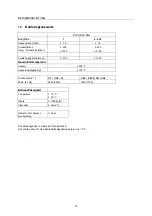
Dates de capacité ........................................................................................................................ 29
2
Sécurité ........................................................................................................................... 29
2.1
Marquage des instructions dans la notice de service ................................................................. 29
2.2
Qualification et Formation du Personnel ..................................................................................... 29
2.3
Dangers en cas de non-respect des instructions de sécurité ..................................................... 30
2.4
Exécution des travaux conforme aux règles de sécuritié............................................................ 30
2.5
Instructions de sécurité pour l’exploitant / le personnel de service ............................................. 30
2.6
Instructions de sécurité pour l’entretien, inspection et travaux de montage ............................... 30
2.7
Modification et fabrication de pièces de rechange non-autoriées ............................................... 30
2.8
Modes de fonctionnement non-admis ......................................................................................... 30
3
Transportation et stockage intermédiaire ................................................................... 31
3.1
Transportation ............................................................................................................................. 31
3.2
Stockage intermédiaire ............................................................................................................... 31
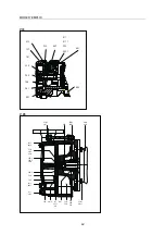
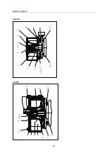
4
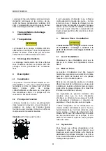
Description ..................................................................................................................... 31
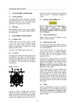
4.1
Constitution ................................................................................................................................. 31
4.2
Principe de Fonction.................................................................................................................... 31
5
Mise en Place / Installation ........................................................................................... 31
5.1
Lieu d’ Installation ........................................................................................................................ 31
5.2
Mise en Place .............................................................................................................................. 31
5.3
Tuyauteries .................................................................................................................................. 31
5.3.1
Tubulure d’aspiration .................................................................................................................................. 32
5.3.2
Tubulure de refoulement ............................................................................................................................ 32
5.4
Branchement électrique .............................................................................................................. 32
5.5
Modes de fonctionnement ........................................................................................................... 32
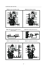
5.5.1
Réfrigération par circulation ouverte ........................................................................................................... 32
5.5.2
Refroidissement par circulation en circuit fermé ......................................................................................... 32
5.5.3
Refroidissement en circuit ouvert ............................................................................................................... 33
5.5.4
Exécution avec éjecteur à gaz ................................................................................................................... 33
5.6
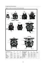
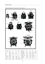
Configuration de l'installation ...................................................................................................... 33
6
Mise en et hors service ................................................................................................. 36
6.1
Préparation pour le service ......................................................................................................... 36
6.2
Mise en service ........................................................................................................................... 36
6.3
Réglage du débit de liquide ......................................................................................................... 36
6.3.1
Refroidissement par circulation en circuit ouvert (Fig. 2a) .......................................................................... 36
6.3.2
Refroidissement par circulation en circuit fermé (Fig. 3) ............................................................................ 36
6.3.3
Refroidissement en circuit ouvert (Fig. 4a) ................................................................................................. 36
6.3.4
Pour installation à fonctionnement automatique (Fig. 2b) .......................................................................... 36
6.4
Mise hors service ........................................................................................................................ 36
7
Exploitation .................................................................................................................... 37
7.1
Généralités .................................................................................................................................. 37
7.2
Besoins en eau fraîche ............................................................................................................... 37
7.3
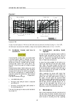
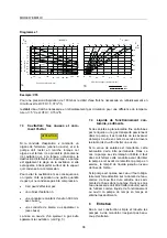
Cavitation: Ses causes et comment l'éviter ................................................................................ 38
7.4
Liquide de fonctionnement contaminé, sédiments ...................................................................... 38
8
Entretien ......................................................................................................................... 38
9
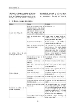
Défauts, causes et remèdes ......................................................................................... 39
10
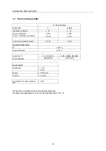
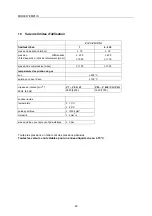
Valeurs limites d’utilisation .......................................................................................... 40
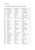
11
Ersatzteilliste / spare parts list / Liste de pièces de rechange .................................. 41


